Fiber optic handling and acceptance criteria
460
ANSI Hardware Installation Manual
3HH-12893-AAAA-TCZZA Issue: 09
DRAFT
The result of an inspection can be one of three conditions:
• preferred
• acceptable
• unacceptable
Table 31 Single-mode end-face inspection acceptance criteria
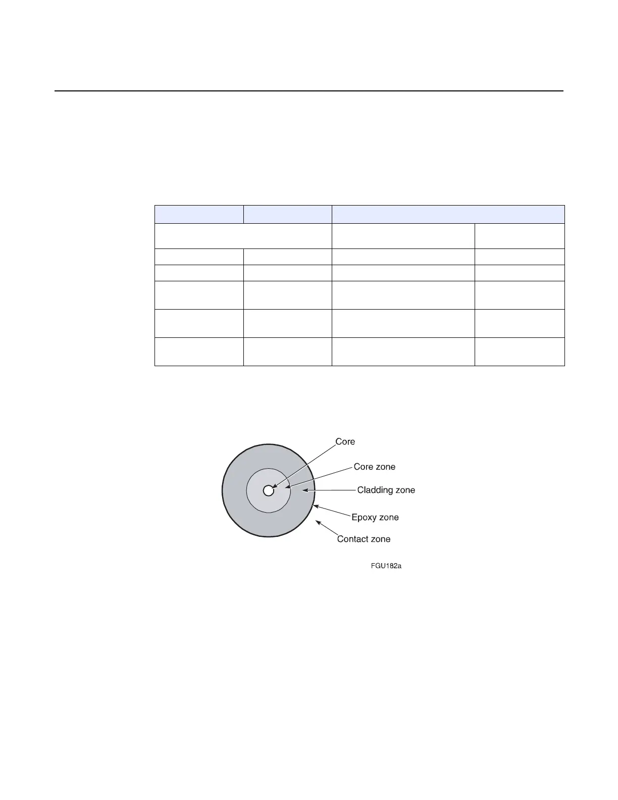
Figure 261 Single-mode end-face zones
The preferred condition of an end-face is shown in Figure 262. There should be no
evidence of contamination, scratches, or any defect. Figure 262 also identifies the
end-face zones shown in Figure 261. For clarity, the zones are not shown to scale,
and the core and core zones are shown as one zone.
Zone Diameter Acceptance criteria (number and size)
Non-removable (contamination of
pits)
Scratches
Core 9 µm None None
Core zone <50 µm None None
Cladding zone 50 to 120 µm Quantity: 3 max.
Diameter: 5 µm max.
Quantity: 2 max.
Width: 2 µm max.
Epoxy zone 120 to 130 µm Quantity: no limit
Diameter: 10 µm
No limit
Contact zone 130 to 250 µm Quantity: no limit
Diameter: 10 µm
No limit

 Loading...