Part Names and Functions
38
FQ2-S/CH User’s Manual
Sensor Data Units
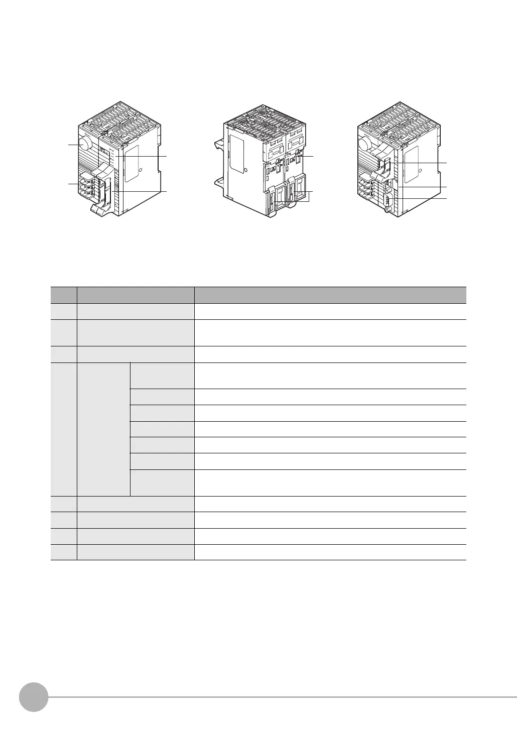
No. Name Description
(1) Sensor connector Connects to the FQ2-S3/S4/CH.
(2) Power supply and
ground terminal block
Connects to the 24-V power source and the ground line.
(3) Parallel I/O connector Connects to the I/O connector.
(4) I/O indicators
POWER/
ERROR
Lights green when power is being supplied.
Lights red when an error occurs.
RUN Lights green during operation.
BUSY Lights yellow when the Sensor is executing a process.
SENSOR Lights yellow when the Sensor is connected.
OR-OK Lights green when the overall judgment result is OK.
OR-NG Lights red when the overall judgment result is OFF or an error occurs.
232C_COM Lights yellow during RS-232C communications.
(Provided only on the FQ-SDU2.)
(5) DIN Track mounting section Mounts the Sensor Data Unit to a DIN Track.
(6) Slider Used to secure the Sensor Data Unit to a DIN Track.
(7) RS-232C connector Connects to the RS-232C connector.
(8) Parallel I/O connector Connects to the I/O connector.
Front Surface of Parallel Interface
Sensor Data Unit
Back Surface of Parallel Interface
Sensor Data Unit
RS-232C Interface
Sensor Data Unit
(1)
(4)
(4)
(8)
(7)
(5)
(3) (6)
(2)

 Loading...


