Part Names and Functions
FQ2-S/CH User’s Manual
35
2
Installation and Connections
2-2 Part Names and Functions
FQ2-S3 FQ2-S4
FQ2-S- (Sensors with Built-in Lighting)
FQ2-CH1-M (Sensors with Built-in Lighting)
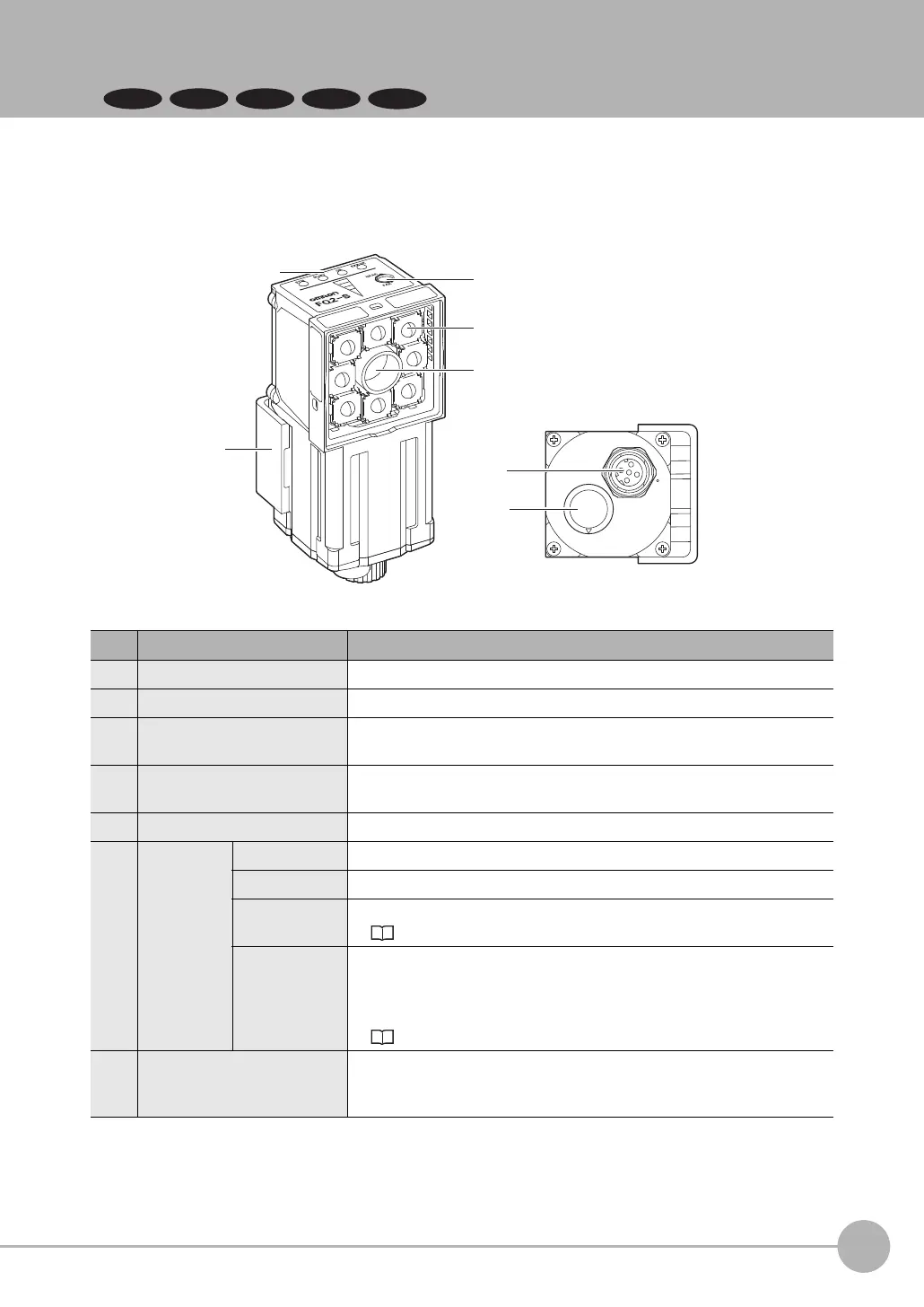
No. Name Description
(1) Lighting LEDs for illumination
(2) Camera lens This lens can be focused.
(3) I/O Cable connector An FQ-WD or FQ-WU I/O Cable is used to connect the Sensor to the power
supply and external I/O.
(4) Ethernet cable connector An FQ-WN Ethernet Cable is used to connect the Sensor to external
devices such as PLCs, the Touch Finder, or computers.
(5) Focus adjustment screw Used to adjust the focus of the image.
(6) Operation
indicators
OR Lights orange when the overall judgment output (OR) signal turns ON.
ETN Lights orange during Ethernet communications.
ERROR Lights red when an error occurs.
8-1 Error Histories: p.432
BUSY
Lights green when the Sensor is executing a process.
* You can change the BUSY indicator to a RUN indicator.
This indicator is set by Default to a BUSY indicator, but if you change it to
a RUN indicator, it will light green during operation.
Changing the Sensor’s BUSY Indicator: p.429
(7) Mounting Bracket
Used to mount the Sensor.
The Mounting Bracket can be attached to the front, left side, right side, or
back of the Sensor.

 Loading...


