Wiring
62
FQ2-S/CH User’s Manual
Connection Method
Align the connector with the socket and press it straight into place, then fix it with the screws on both sides of
the connector.
Turn OFF the power supply before connecting or disconnecting a Cable.
Peripheral devices may be damaged if the cable is connected or disconnected with the power ON.
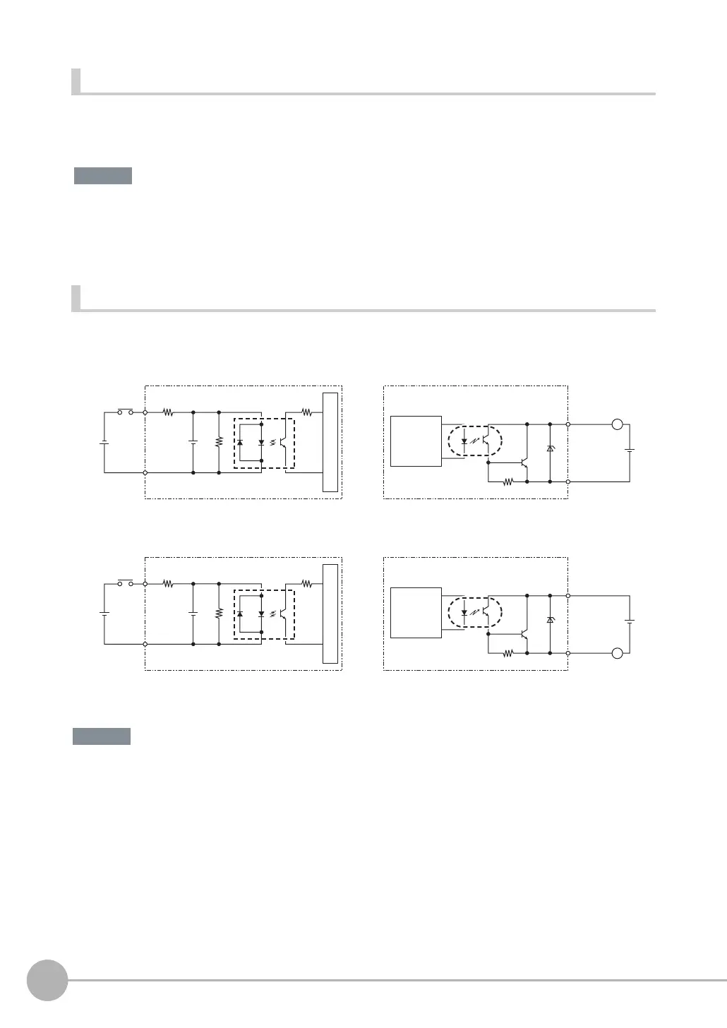
I/O Signal Circuit Diagrams
Preventing Chattering
• The Sensor is equipped with an anti-chattering function, but if the chattering is 100 μs or longer, a faulty input may
occur. (Input signals of 99 μs or shorter are ignored. Signals of 100 μs or longer are treated as input signals.)
• Use no-contact output devices (e.g., SSR or PLC transistor output) for the input signals. If contacts (e.g., a relay)
are used, chattering may cause the trigger to be input again during execution of a measurement.
NPN
PNP
3 KΩ
910 Ω
1000 pF
COM_IN
Input terminal
+
Input Circuit
Internal circuits
Output terminal
Load
Output Circuit
L
COM_OUT
+
Internal
circuits
3 KΩ
910 Ω
1000 pF
COM_IN
Input terminal
+
Input Circuit
Internal circuits
Output terminal
Load
Output Circuit
L
COM_OUT
+
Internal
circuits

 Loading...


