Wiring
FQ2-S/CH User’s Manual
59
2
Installation and Connections
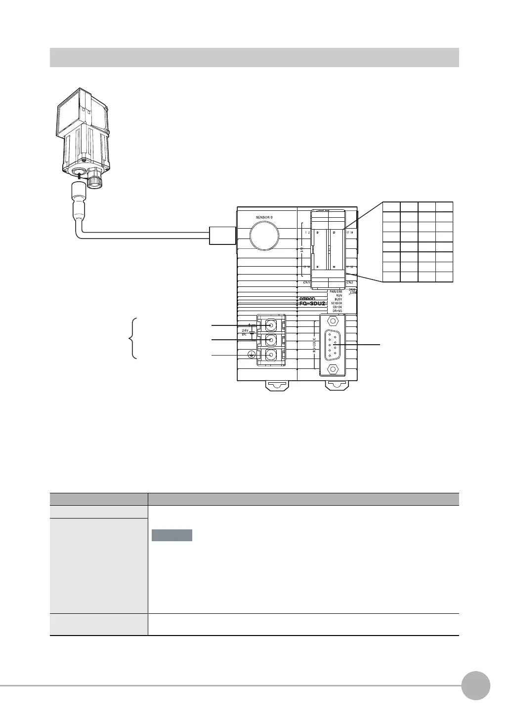
RS-232C Interface Sensor Data Unit (FQ-SDU2)
For the I/O connector harness, use an FQ-VP2 Parallel Cable for the FQ-SDU2 or a MIL-standard
harness, such as the OMRON XZ2F. (The Cables are sold separately.)
Pins 1 to 16 and pins 17 to 32 are for separate connectors. One FQ-VP2is required for each connector.
Signal Application
Power supply (24 V)
These terminals are for the external power supply (24 V).
• Wire the power supply separately from other devices. If the wiring for other devices is
placed together or in the same duct as the wiring for the Sensor, the influence of elec-
tromagnetic induction may cause the Sensor to malfunction or may damage it.
• Do not allow the load current to exceed 50 mA. The output circuit may be damaged if
the load current exceeds 50 mA.
Power supply (0 V)
Frame ground
This is the frame ground terminal.
Connect the ground wire by a D-type ground (ground resistance of 100Ω or less).
FQ2-S3
@@@@@
-
@@@
FQ2-S4
@@@@@
-
@@@
FQ2-CH1
@@@@@
-M
(Sensors with Built-in Lighting or Sensors with
C-mounts)
Power supply (24 V)
Power supply (0 V)
Frame ground
RS-232C connector
1 2 17 18
3 4 19 20
5 6 21 22
7 8 23 24
9 10 25 26
11 12 27 28
13 14 29 30
15 16 31 32
(Screw size: M3,
Tightening torque:
0.54 N·m)
FQ-WU0
Sensor Data Unit Cable
Important

 Loading...


