© Precor Incorporated, Unauthorized Reproduction and Distribution Prohibited by Law
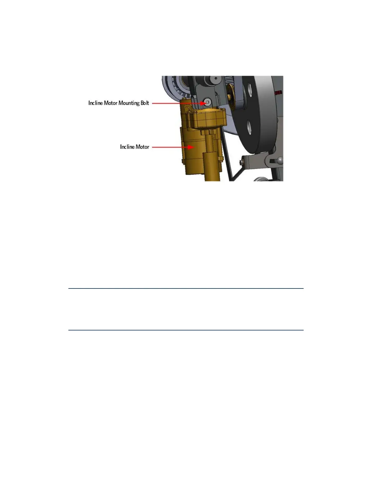
Figure 297: Incline Motor Mounting
46 Connect the incline motor cable connector to the lower PCA and
replace the lower PCA cover as per procedure, Replacing the Lower PCA
and Battery Bracket (on page 270).
47 Access the incline Lift Test portion of the Diagnostic Program, see
Accessing the P30 Diagnostic Software (on page 13), P80 Settings (on page
51).
48 With the lift incline number displayed, set the incline to level 2
using the STRIDE HEIGHT and STRIDE HEIGHT keys
49 Rotate the incline motor tube on the incline motor drive screw until
the measurement between the top of the incline nut and the end of
the incline motor drive screw is 1-1/4 inches.
Note: When rotating the incline motor tube, do not allow the incline
motor drive screw to rotate. If the incline motor drive screw rotates, the
lift level number will change. The lift level number must be 2 and the
physical measurement must be 1-1/4 inches for the calibration to be
correct.
 Loading...