© Precor Incorporated, Unauthorized Reproduction and Distribution Prohibited by Law
3 Access the incline Lift Test portion of the Diagnostic Program, see
Accessing the P30 Diagnostic Software (on page 13), P80 Settings (on page
51).
4 With the lift incline number displayed, set the incline to level 2
using the STRIDE HEIGHT and STRIDE HEIGHT keys
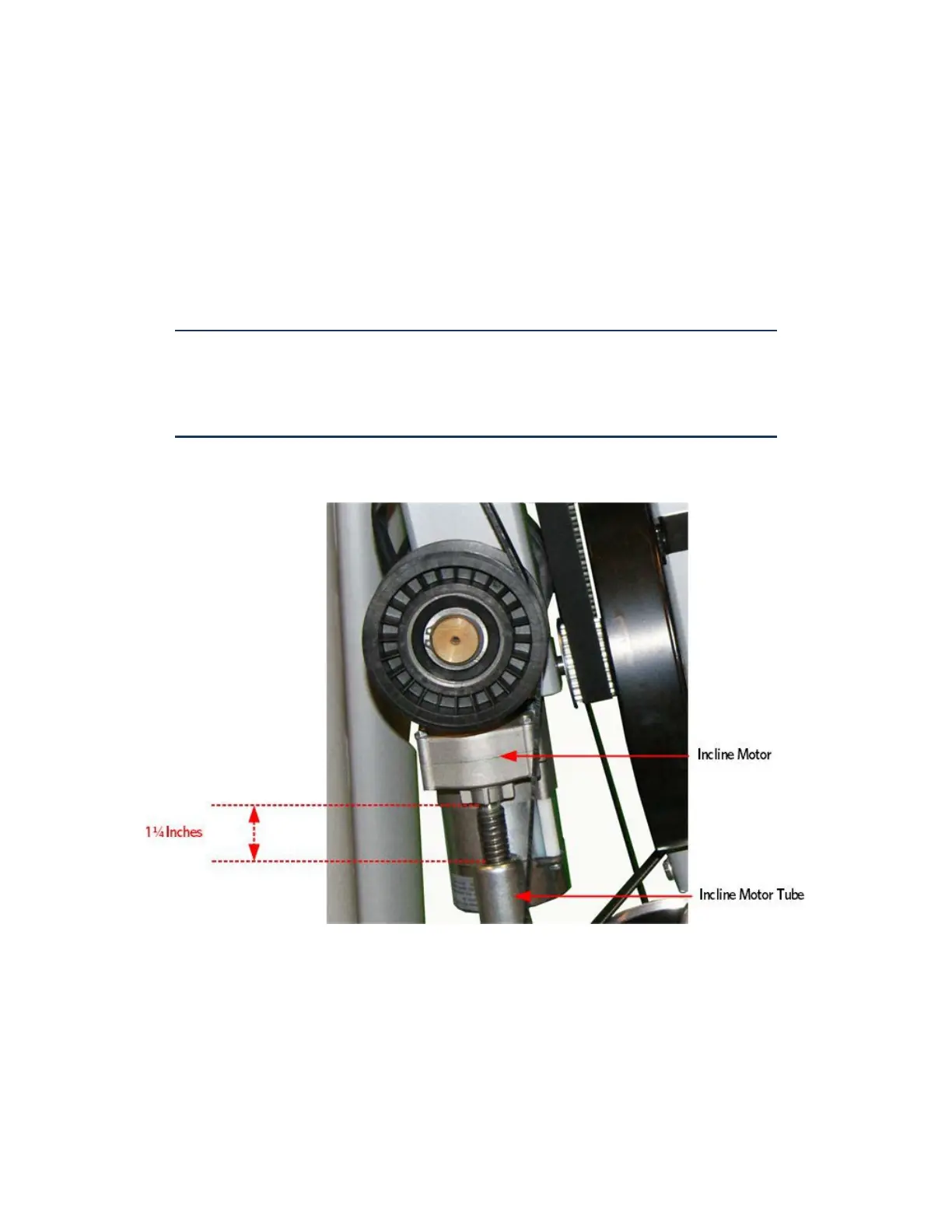
5 Rotate the incline motor tube on the incline motor drive screw until
the measurement between the top of the incline nut and the end of
the incline motor drive screw is 1-1/4 inches.
Note: When rotating the incline motor tube, do not allow the incline
motor drive screw to rotate. If the incline motor drive screw rotates, the
lift level number will change. The lift level number must be 2 and the
physical measurement must be 1-1/4 inches for the calibration to be
correct.
Figure 321: Incline Motor Calibration Measurement
Gas Shock Installation
6 Rotate the gas shock up.
7 Adjust the height of the gas shock by lowering or raising the front
of the Incline platform until the gas shock and the upper mounting
stud align.
8 Press the gas shock onto the mounting stud and secure the gas shock
to the upper mounting stud by pushing in on the tension clip.
 Loading...