RL78/F13, F14 CHAPTER 16 SERIAL INTERFACE IICA
R01UH0368EJ0210 Rev.2.10 1096
Dec 10, 2015
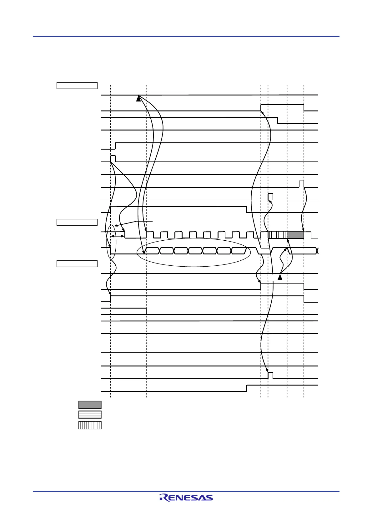
Figure 16-33. Example of Slave to Master Communication
(When 8-Clock Wait Is Selected for Master, 9-Clock Wait Is Selected for Slave) (1/3)
(1) Start condition ~ address ~ data
IICA0
STT0
(ST trigger)
SPT0
(SP trigger)
ACKD0
(ACK detection)
WTIM0
(8 or 9 clock wait)
ACKE0
(ACK control)
MSTS0
(communication status)
TRC0
(transmit/receive)
SCLA0 (bus)
(clock line)
WREL0
(wait cancellation)
INTIICA0
(interrupt)
SDAA0 (bus)
(data line)
AD6
D
1
7
R
ACK
IICA0
STD0
(ST detection)
SPD0
(SP detection)
ACKD0
(ACK detection)
WTIM0
(8 or 9 clock wait)
ACKE0
(ACK control)
MSTS0
(communication status)
TRC0
(transmit/receive)
WREL0
(wait cancellation)
INTIICA0
(interrupt)
Master side
Bus line
Slave side
Slave address
L
L
H
H
H
L
AD5 AD4 AD3 AD2 AD1 AD0
Start condition
Note 2
Note 1
Note 3
<2>
<5>
<1>
<7>
<3>
<4>
<6>
: Wait state by master device
: Wait state by slave device
: Wait state by master and slave devices
Notes 1. For releasing wait state during reception of a master device, write “FFH” to IICA0 or set the WREL0 bit.
2. Make sure that the time between the fall of the SDAA0 pin signal and the fall of the SCLA0 pin signal is
at least 4.0
s when specifying standard mode and at least 0.6
s when specifying fast mode.
3. Write data to IICA0, not setting the WREL0 bit, in order to cancel a wait state during transmission by a
slave device.

 Loading...


