RL78/F13, F14 CHAPTER 17 LIN/UART MODULE (RLIN3)
R01UH0368EJ0210 Rev.2.10 1181
Dec 10, 2015
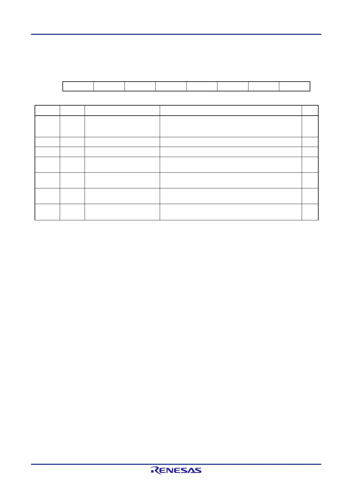
(16) LIN/UART Status Register (LSTn)
Address: F06D2H
7 6 5 4 3 2 1 0
— — URS UTS ERR — — FTC
Value after reset:
0 0 0 0 0 0 0 0
Bit Symbol Bit Name Function R/W
0 FTC Successful Buffer Transmission
Flag
0: Data transmission from the UART buffer has not been
completed.
1: Data transmission from the UART buffer has been completed.
R/W
1 — Reserved This bit is always read as 0. The write value should always be 0. R/W
2 — Reserved This bit is always read as 0. The write value should always be 0. R/W
3 ERR Error Detection Flag 0: No error has been detected.
1: Error has been detected.
R
4 UTS Transmission Status Flag 0: The LIN/UART module is not transmitting data.
1: The LIN/UART module is transmitting data.
R
5 URS Reception Status Flag 0: The LIN/UART module is not receiving data.
1: The LIN/UART module is receiving data.
R
7, 6 — Reserved These bits are always read as 0. The write value should always
be 0.
R/W
The LSTn register is automatically cleared to 00H upon transition to LIN reset mode.
In LIN reset mode, writing to this register is disabled. In LIN reset mode, the register retains 00H.
To clear the specific bits in the register, write 0 to the bits to be cleared and write 1 to the other bits by using an 8-bit data
transfer instruction.
FTC flag (successful buffer transmission flag)
Only 0 can be written to the FTC flag; when 1 is written, the bit retains the value that has been retained before 1 is written.
Whether or not an error has occurred, this bit is set to 1 upon completion of transmission of data, which is equal to the
number of data units set with the MDL bits in the LDFCn register, from UART buffer. Here, an interrupt is generated.
To clear the bit to 0, write 0 to the bit.
ERR flag (error detection flag)
The ERR flag is set to 1 upon detection of an error (any of the LESTn register flags is 1). Here, an interrupt is generated.
Note that when an error, the expansion bit, or ID match is detected with the ERR flag set to 1, an interrupt is not generated.
To clear the bit to 0, write 0 to the UPER, IDMT, EXBT, FER, OER, and BER flags in the LESTn register. This clears the
ERR flag to 0.
UTS flag (transmission status flag)
The UTS flag is set to 1 upon start of transmission. During transmission, the flag retains 1.
Transmission is started when:
transmission data is set in the LUTDRn or LUWTDRn register.
1 is set in the RTS bit in the LTRCn register.
The UTS flag is cleared to 0 upon end of transmission. While transmission is halted, the flag retains 0.
Transmission is ended when:
transmission of the data set in the LUTDRn or LUWTDRn register is completed and the next transmission data is not
set.
data transmission from the UART buffer is completed (the RTS bit in the LTRCn register is set to 0 ).
<R>
 Loading...


