RL78/F13, F14 CHAPTER 17 LIN/UART MODULE (RLIN3)
R01UH0368EJ0210 Rev.2.10 1194
Dec 10, 2015
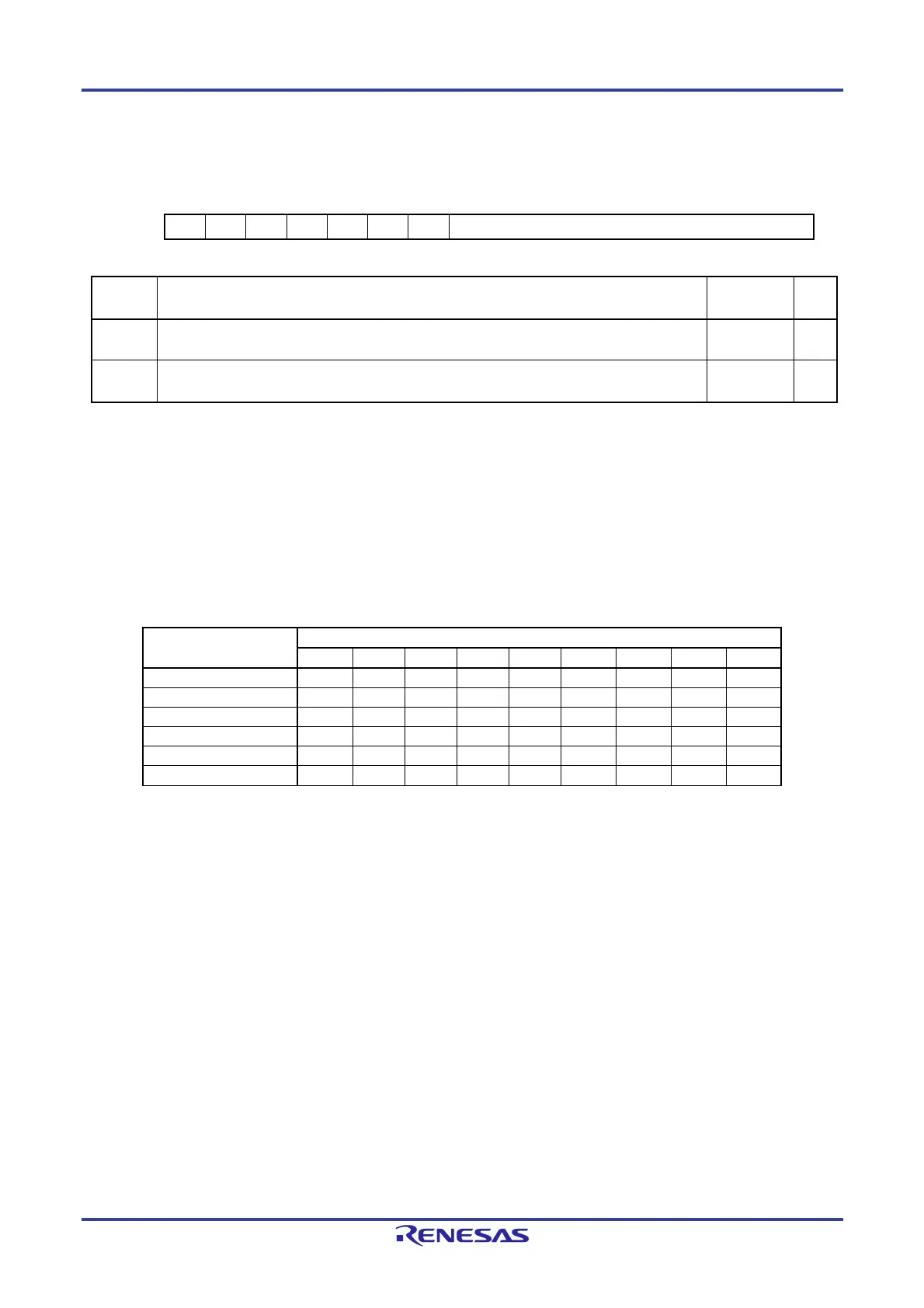
(26) UART Wait Transmission Data Register (LUWTDRn)
Address: F06E9H, F06E8H
15 14 13 12 11 10 9 8 7 6 5 4 3 2 1 0
— — — — — — — [8:0]
Value after reset:
0 0 0 0 0 0 0 0 0 0 0 0 0 0 0 0
Bit Function
Setting
Range
R/W
8 to 0 Sets the data to be transmitted from the UART wait transmission data register after waiting for
the stop bit reception to be completed.
000H to
1FFH
R/W
15 to 9 Reserved.
These bits are always read as 0. The write value should always be 0.
— R/W
The LUWTDRn register sets the data to be transmitted from the UART wait transmission data register.
Writing data to this register with the UTOE bit in the LUOERn register set to 1 starts transmission.
Use this register only to switch from reception to transmission in half-duplex communication.
The user should write to this register only while the stop bit is received.
Note that the wait time is only 1 bit even if the stop bit length is set to 2 bits with the USBLS bit in the LBFCn register.
When this register is read, the LUTDRn register value is actually read.
In 9-bit communication mode, do not attempt 8-bit access.
Do not write data to this register when data transmission from the UART buffer is in progress.
The table below shows the bit arrangement according to the set transfer format.
Item
LUWTDRn
8 7 6 5 4 3 2 1 0
7-bit; LSB first — — Bit 6 Bit 5 Bit 4 Bit 3 Bit 2 Bit 1 Bit 0
7-bit; MSB first — — Bit 0 Bit 1 Bit 2 Bit 3 Bit 4 Bit 5 Bit 6
8-bit; LSB first — Bit 7 Bit 6 Bit 5 Bit 4 Bit 3 Bit 2 Bit 1 Bit 0
8-bit; MSB first — Bit 0 Bit 1 Bit 2 Bit 3 Bit 4 Bit 5 Bit 6 Bit 7
9-bit; LSB first Bit 8 Bit 7 Bit 6 Bit 5 Bit 4 Bit 3 Bit 2 Bit 1 Bit 0
9-bit; MSB first Bit 0 Bit 1 Bit 2 Bit 3 Bit 4 Bit 5 Bit 6 Bit 7 Bit 8

 Loading...


