RL78/F13, F14 CHAPTER 19 DTC
R01UH0368EJ0210 Rev.2.10 1455
Dec 10, 2015
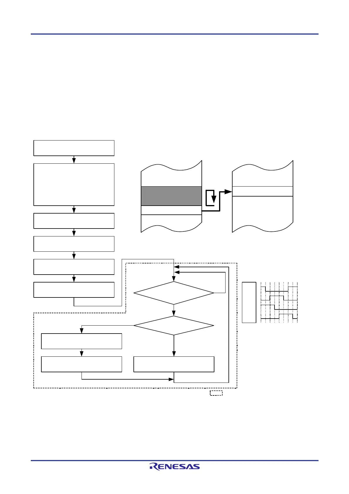
(1) Example 1 of using repeat mode: Outputting a stepping motor control pulse using ports
The DTC is activated by an interval timer interrupt and the pattern of the motor control pulse stored in the code flash
memory is transferred to general-purpose ports.
The vector address is FFC17H and control data is allocated at FFCD0H to FFCD7H.
The timer interrupt is assigned to source number 23.
Transfers 8-byte data of 02000H to 02007H of the code flash memory from the mirror space (F2000H to F2007H)
to port register 1 (FFF01H).
A repeat mode interrupt is disabled.
Figure 19-24. Example 1 of Using Repeat Mode: Outputting a Stepping Motor Control Pulse Using Ports
Port register 1
Vector address (FFC17H) = D0H
DTCCR18 (FFCD0H) = 03H
DTBLS18 (FFCD1H) = 01H
DTCCT18 (FFCD2H) = 08H
DTRLD18 (FFCD3H) = 08H
DTSAR18 (FFCD4H) = 2000H
DTDAR18 (FFCD6H) = FF01H
No
Yes
Yes
No
P13
P12
P11
P10
2007H
2000H
DTCBAR = FCH
DTCEN20 = 1
Timer setting
Setting P10 to P13 to output mode
Starting timer operation
Data transfer
DTCCT18 = DTRLD18 Data transfer
DTCCT18 = 01H?
Interval timer interrupt?
Code flash
To stop the output, stop the timer first and then clear DTCEN20.
The processing shown inside the dotted
line is automatically executed by the DTC.
Example of 1-2 phase excitation
 Loading...


