RL78/F13, F14 APPENDIX B REVISION HISTORY
R01UH0368EJ0210 Rev.2.10 1842
Dec 10, 2015
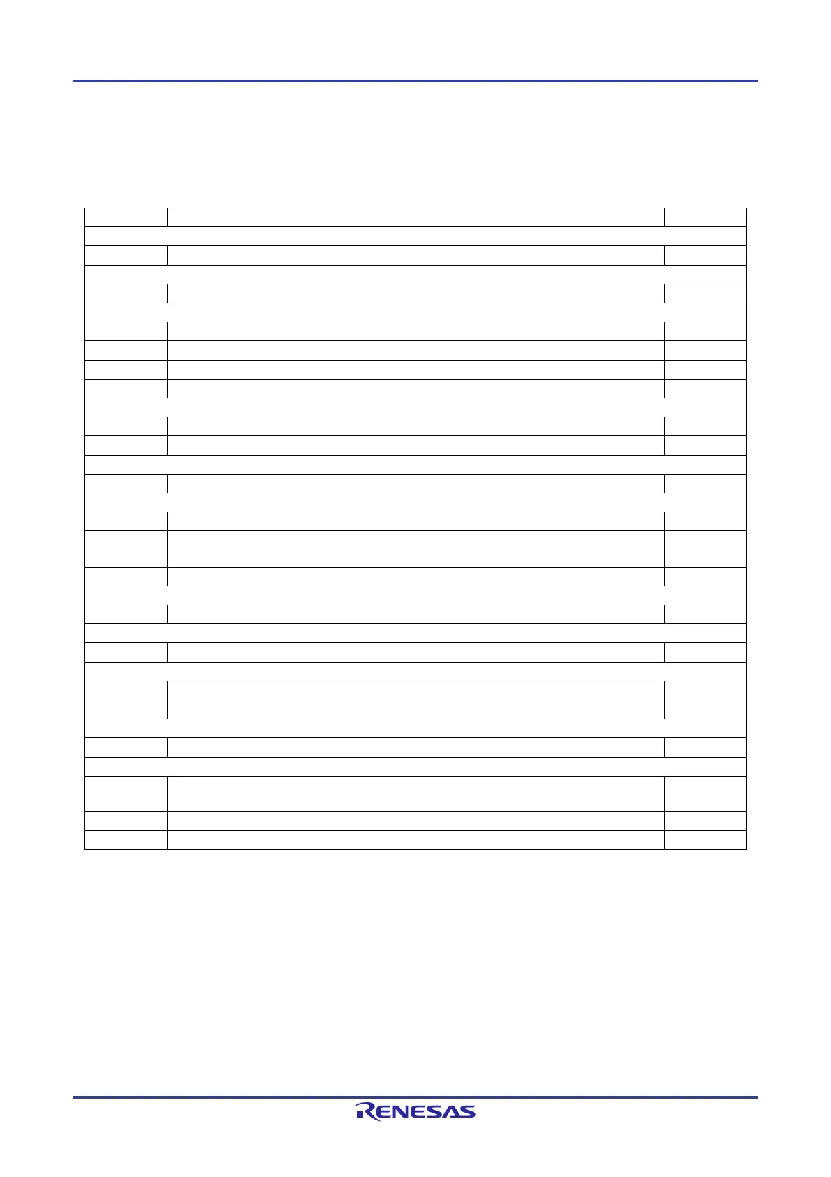
APPENDIX B REVISION HISTORY
Major Revisions in This Edition
(1/3)
Page Description Classification
CHAPTER 1 OVERVIEW
p.10 to 31 Figure 1-1 to 1-22 Block Diagram, added other products (c)
CHAPTER 3 CPU ARCHITECTURE
p.147 Table 3-5 SFR List (1/4), corrected After Reset value of P13 register (c)
CHAPTER 4 PORT FUNCTIONS
p.256 4.2.7 Port 7, corrected PMC7 register (a)
p.271 Table 4-14 Setting Functions of P80/ANI2/ANO0 Pin, corrected (c)
p.321 Figure 4-75 Format of Port Register, corrected After Reset value of P13 register (c)
p.325 Figure 4-79 Format of Port Mode Control Register, added Note of PMC7 register (c)
CHAPTER 5 CLOCK GENERATOR
p.389 Figure 5-18 Format of LIN Clock Select Register (LINCKSEL), added Caution 3 (c)
p.423 5.7.2 High-Speed On-Chip Oscillator, corrected high-speed on-chip oscillator frequency (a)
CHAPTER 6 TIMER ARRAY UNIT
p.438 6.2.2 Timer data register mn (TDRmn), added description (c)
CHAPTER 8 TIMER RD
p.569 Table 8-2 Timer RD Register Configuration, corrected Access Size of TRDCR1 register (a)
p.602 8.2.19 Timer RD General Registers Ai, Bi, Ci, and Di (TRDGRAi, TRDGRBi, TRDGRCi, TRDGRDi)
[Complementary PWM Mode], deleted TRDDF0 and TRDDF1 register
(a)
p.621 Figure 8-44 Pulse Output Forced Cutoff, corrected INTP0 circuit (a)
CHAPTER 9 REAL-TIME CLOCK
p.666 Figure 9-8 Format of Real-time Clock Control Register 1 (RTCC1), added Note 1 and 2 of RWAIT bit (b)
CHAPTER 11 WATCHDOG TIMER
p.697 Table 11-3 Setting of Overflow Time of Watchdog Timer, added Note (b)
CHAPTER 12 A/D CONVERTER
p.703 12.2 (1) ANI0 to ANI23 (V
DD
) and ANI24 to ANI30 (EV
DD
) pins, corrected Note (a)
p.730 Figure 12-18 Formats of Port Mode Control Registers 7, 9 and 12, added Note of PMC7 register (c)
CHAPTER 13 D/A CONVERTER (RL78/F14 Only)
p.772 Table 13-1 Setting Functions of ANO0/ANI2/P80 Pin, corrected (c)
CHAPTER 15 SERIAL ARRAY UNIT
p.792,833,895,
959,992
Note of Tables “Group A, B, C-1, C-2, D-1, D-2 and E” (b)
p.807 Note of Figure 15-7. Format of Serial Communication Operation Setting Register mn (SCRmn) (b)
p.821 Note of Figure 15-17. Format of Serial Slave Select Enable Register m (SSEm) (b)
Remark: “Classification” in the above table classifies revisions as follows.
(a): Error correction, (b): Addition/change of specifications, (c): Addition/change of description or note,
(d): Addition/change of package, part number, or management division, (e): Addition/change of related documents

 Loading...


