RL78/F13, F14 CHAPTER 6 TIMER ARRAY UNIT
R01UH0368EJ0210 Rev.2.10 537
Dec 10, 2015
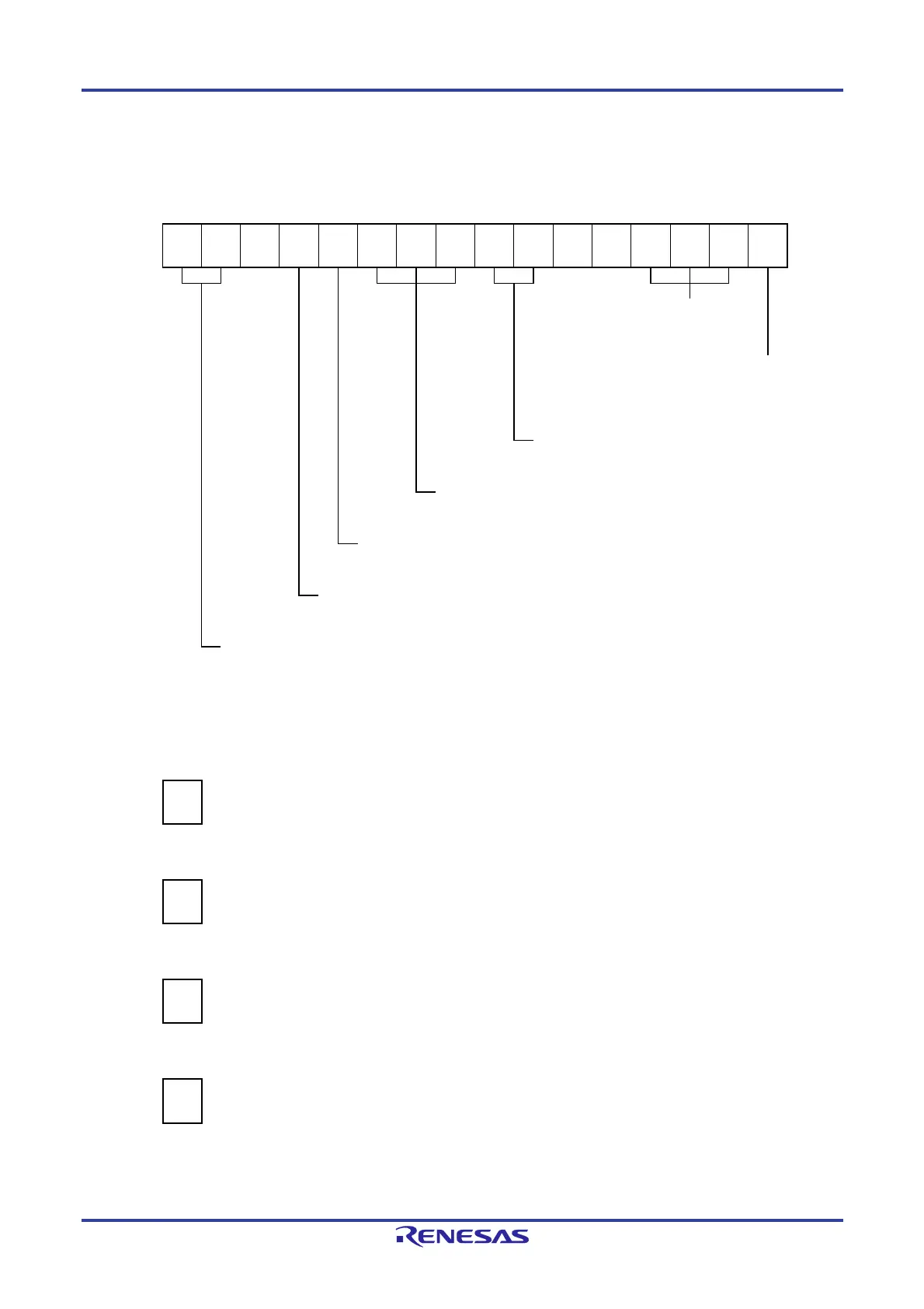
Figure 6-79. Example of Set Contents of Registers
When Multiple PWM Output Function (Master Channel) Is Used
(a) Timer mode register mn (TMRmn)
15 14 13 12 11 10 9 8 7 6 5 4 3 2 1 0
TMRmn
CKSmn1
1/0
CKSmn0
1/0
0
CCSmn
0
MAS
TERmn
1
STSmn2
0
STSmn1
0
STSmn0
0
CISmn1
0
CISmn0
0
0
0
MDmn3
0
MDmn2
0
MDmn1
0
MDmn0
1
Operation mode of channel n
000B: Interval timer
Setting of operation when counting is started
1: Generates INTTMmn when counting is
started.
Selection of TImn pin input edge
00B: Sets 00B because these are not used.
Start trigger selection
000B: Selects only software start.
Slave/master selection
1: Master channel.
Count clock selection
0: Selects operation clock (f
MCK).
Operation clock (f
MCK) selection
00B: Selects CKm0 as operation clock of channel n.
01B: Selects CKm2 as operation clock of channel n.
10B: Selects CKm1 as operation clock of channel n.
11B: Selects CKm3 as operation clock of channel n.
(b) Timer output register m (TOm)
Bit n
TOm
TOmn
0
0: Outputs 0 from TOmn.
(c) Timer output enable register m (TOEm)
Bit n
TOEm
TOEmn
0
0: Stops the TOmn output operation by counting operation.
(d) Timer output level register m (TOLm)
Bit n
TOLm
TOLmn
0
0: Cleared to 0 when TOMmn = 0 (master channel output mode).
(e) Timer output mode register m (TOMm)
Bit n
TOMm
TOMmn
0
0: Sets master channel output mode.
Remarks 1. m: Unit number (m = 0, 1), n: Master channel number (n = 0, 2, 4)
2. Unit 1 is not provided in the Group A products.
Channels 7 to 4 of unit 1 are not provided in the Group B, C, and D products.
 Loading...


