RL78/F13, F14 CHAPTER 6 TIMER ARRAY UNIT
R01UH0368EJ0210 Rev.2.10 538
Dec 10, 2015
Figure 6-80. Example of Set Contents of Registers
When Multiple PWM Output Function (Slave Channel) Is Used (output two types of PWMs)
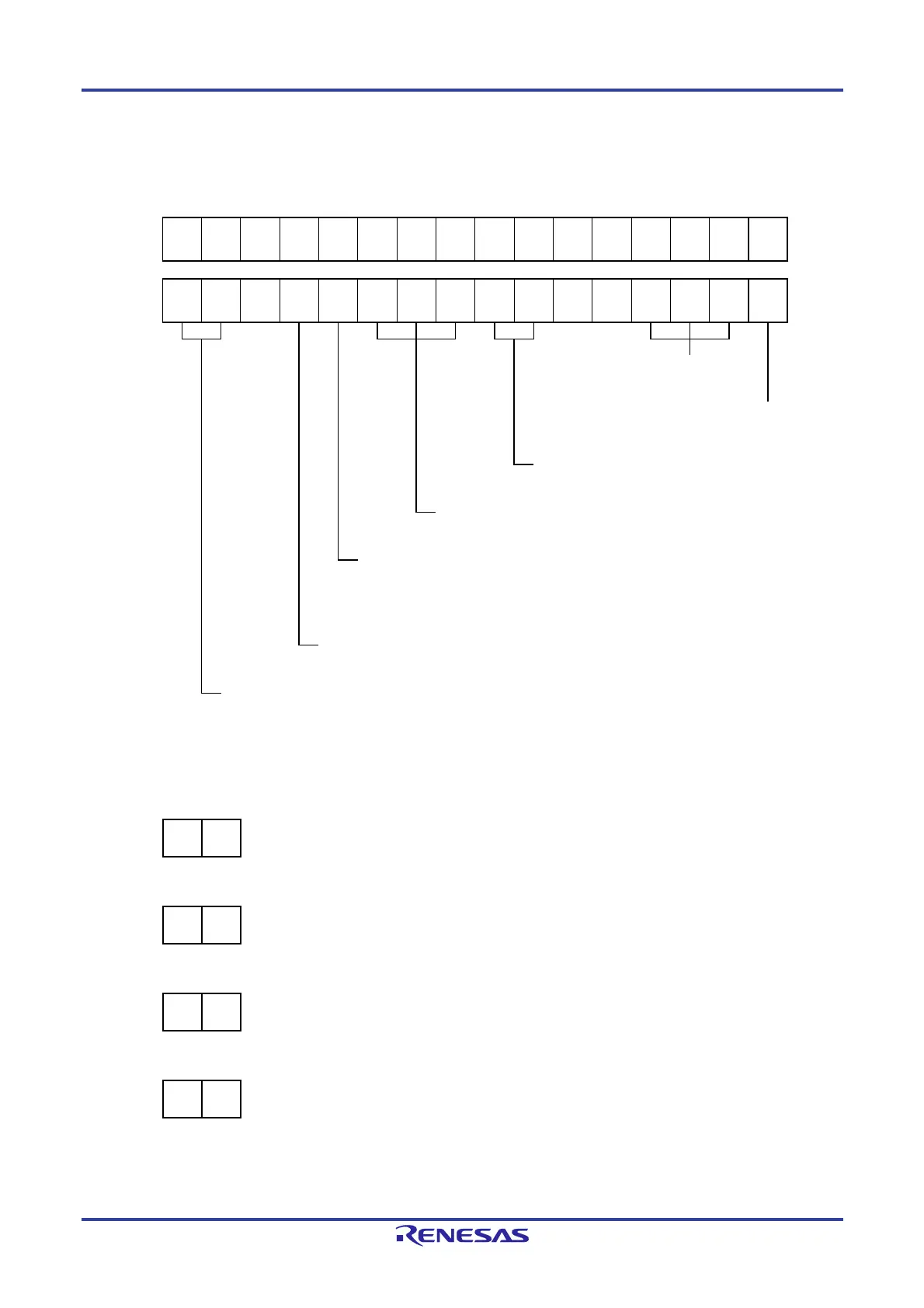
(a) Timer mode register mp, mq (TMRmp, TMRmq)
15 14 13 12 11 10 9 8 7 6 5 4 3 2 1 0
TMRmp
CKSmp1
1/0
CKSmp0
1/0
0
CCSmp
0
M/S
Note
0
STSmp2
1
STSmp1
0
STSmp0
0
CISmp1
0
CISmp0
0
0
0
MDmp3
1
MDmp2
0
MDmp1
0
MDmp0
1
15 14 13 12 11 10 9 8 7 6 5 4 3 2 1 0
TMRmq
CKSmq1
1/0
CKSmq0
1/0
0
CCSmq
0
M/S
Note
0
STSmq2
1
STSmq1
0
STSmq0
0
CISmq1
0
CISmq0
0
0
0
MDmq3
1
MDmq2
0
MDmq1
0
MDmq0
1
Operation mode of channel p, q
100B: One-count mode
Start trigger during operation
1: Trigger input is valid.
Selection of TImp and TImq pins input edge
00B: Sets 00B because these are not used.
Start trigger selection
100B: Selects INTTMmn of master channel.
Setting of MASTERmp, MASTERmq bits (channels 2, 4, 6)
0: Slave channel.
Setting of SPLITmp, SPLITmq bits (channels 1, 3)
0: 16-bit timer mode.
Count clock selection
0: Selects operation clock (f
MCK).
Operation clock (fMCK) selection
00B: Selects CKm0 as operation clock of channel p, q.
01B: Selects CKm2 as operation clock of channel p, q.
10B: Selects CKm1 as operation clock of channel p, q.
11B: Selects CKm3 as operation clock of channel p, q.
* Make the same setting as master channel.
(b) Timer output register m (TOm)
Bit q Bit p
TOm
TOmq
1/0
TOmp
1/0
0: Outputs 0 from TOmp or TOmq.
1: Outputs 1 from TOmp or TOmq.
(c) Timer output enable register m (TOEm)
Bit q Bit p
TOEm TOEmq
1/0
TOEmp
1/0
0: Stops the TOmp or TOmq output operation by counting operation.
1: Enables the TOmp or TOmq output operation by counting operation.
(d) Timer output level register m (TOLm)
Bit q Bit p
TOLm TOLmq
1/0
TOLmp
1/0
0: Positive logic output (active-high)
1: Negative logic output (active-low)
(e) Timer output mode register m (TOMm)
Bit q Bit p
TOMm TOMmq
1
TOMmp
1
1: Sets the slave channel output mode.
Note TMRm5, TMRm7: Fixed to 0
TMRm1, TMRm3: SPLITmp, SPLITmq bit
 Loading...


