●Install the bearing at the corresponding position
according to the following method.
○Lock the steering lever nut with a locking torque of
55 N·m first and then loosen it for a
small circle (less
than one circle) to enable the nut to rotate slightly. And
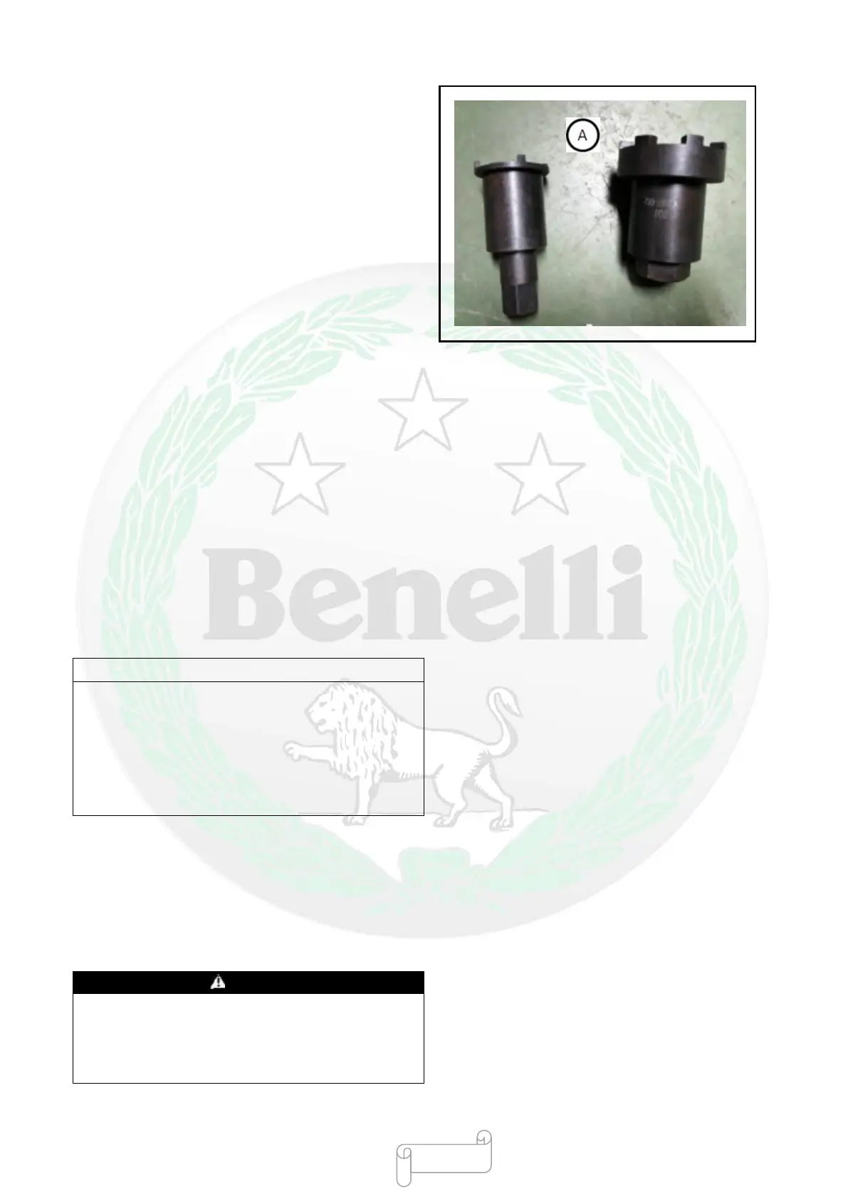
then lock it with a steering lever nut wrench [A] in
accordance with the specified locking torque.
Special Tool—Steering Lever Nut Wrench
(Seven-claw):
Locking torque of steering lever nut: 30-35 N·m
●Tighten the steering lever lock nut manually until the
lock nut touches the steering lever nut.
●Tighten the steering lever lock nut.
Special Tool—Steering Lever Nut Wrench
(Four-claw):
Locking torque of steering lever nut: 20-24N·m
●Install the upper bracket and tighten the steering lever
lock bolt.
●Install the front shock absorber (see “Suspension
System”—“Installing Front Shock Absorber”).
Remark
○Lock the front shock absorber lock bolt at the upper
side, then lock the upper bracket lock nut and lock the
front shock absorber lock bolt at the lower side finally.
○Lock two front shock absorber lock bolts at the lower
side twice alternately to ensure that the locking torque
is even.
Locking torque:
Front shock absorber lock bolt (at the upper side):
22 N·m
Upper bracket lock nut: 78 N·m
Front shock absorber lock bolt (at the lower side):
22 N·m
Please connect the cable, wire harness and hose
properly (see “Appendix”—
Cable, Wire and
Hose”), otherwise the normal
rotation of handlebar will be affected.
- 363 -