162 HEIDENHAIN Technical Manual MANUALplus 620
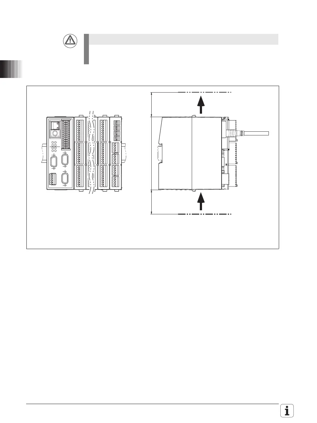
3.2.8 PLB 6xxx mounting position
When mounting, please observe proper minimum clearance, space require-
ments, length and position of the connecting cables.
Leave space for air circulation and
servicing!
Air in
Air out
PLB 6xxx