January 2012 3.17 PROFIBUS Connection 237
3.17 PROFIBUS Connection
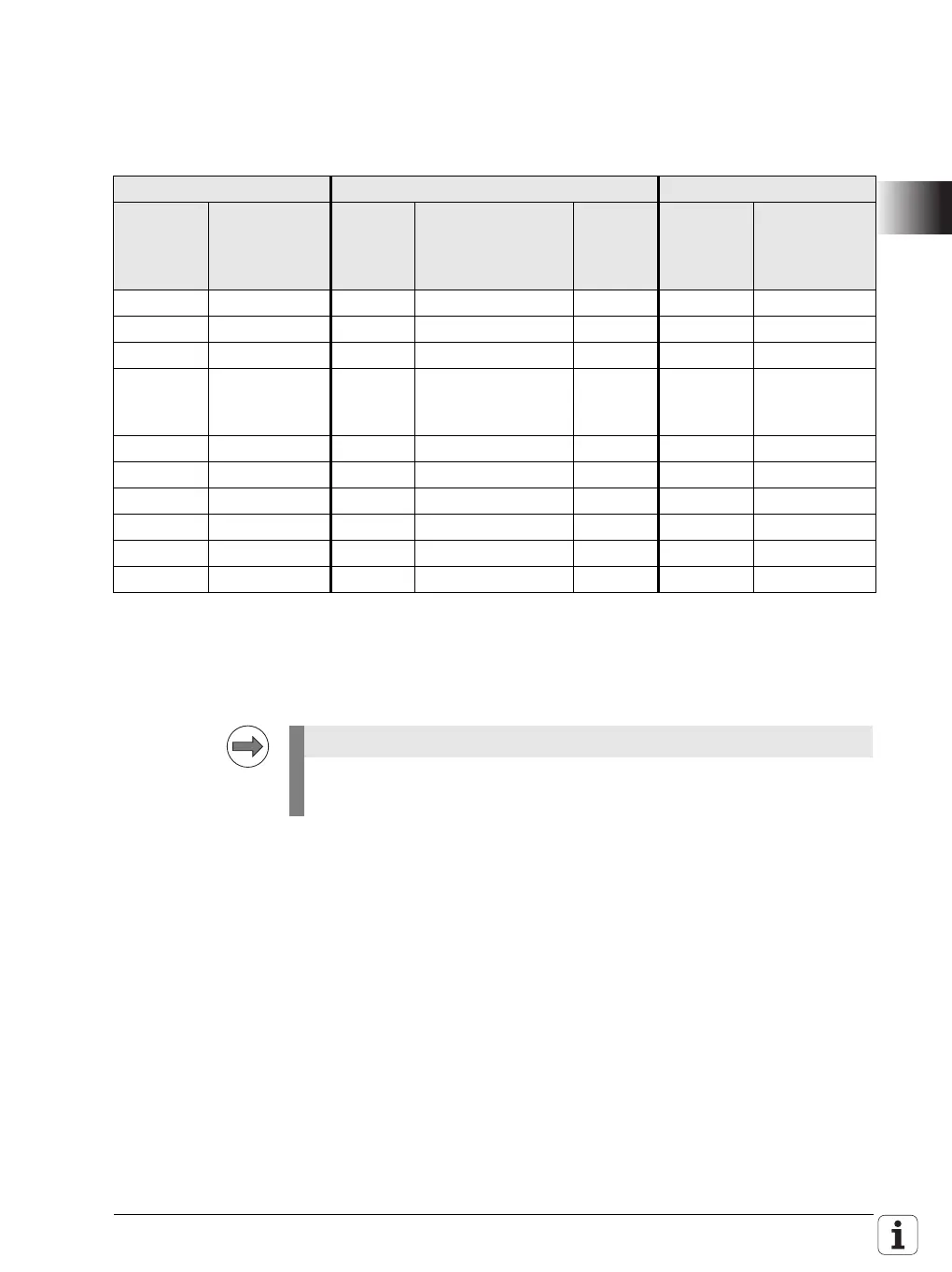
Pin layout on X121 of the MC main computer or IPC and on X1 of the PLB 550
PROFIBUS slave
All signals on the PL 550 are electrically isolated.
All signals are electrically isolated at X121 of the MC 6xxx main computer or
the IPC 6xxx.
The +5 V and GND pins supply the terminating resistor in the connector.
Main computer X121 Connecting cable 515 845-01 PLB 550 X1
D-sub
connctn.
(female)
9-pin
Assignment D-sub
cnnctr.
(male)
9-pin
D-sub
cnnctr.
(male)
9-pin
X1 D-sub
cnnctn.
(female)
9-pin
Assignment
1 Do not assign 1 – 1 1 Do not assign
2 Do not assign 2 – 2 2 Do not assign
3 B line 3 B line 3 3 B line
4RTS
(signal type:
TTL)
4– 44 RTS
(signal type:
TTL)
5 GND 5– 55 GND
6 +5V 6– 66 +5V
7 Do not assign 7 – 7 7 Do not assign
8 A line 8 A line 8 8 A line
9 Do not assign 9 – 9 9 Do not assign
Housing External shield Housing External shield Housing Housing External shield
For more information about PROFIBUS on HEIDENHAIN controls, refer to
the documentation about the IOconfig software for PCs.

 Loading...


