174 HEIDENHAIN Technical Manual MANUALplus 620
3.5.3 CC 6108
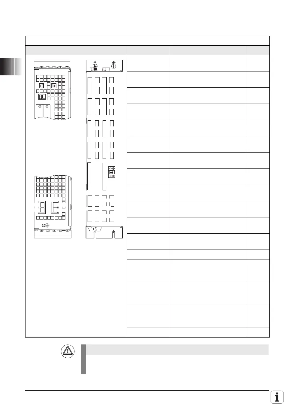
CC 6108 controller unit with 8 control loops and HSCI interface
Pin layout Connector Function Page
X15A to X18A Speed encoder
Drive-control motherboard A
246
X15B to X18B Speed encoder
Drive-control motherboard B
246
X51A to X54A PWM output
Drive-control motherboard A
254
X51B to X54B PWM output
Drive-control motherboard B
254
X69A Supply bus
Drive-control motherboard A
186
X69B Supply bus
Drive-control motherboard B
186
X201A to
X204A
Position encoder
Drive-control motherboard A
243
X201B to
X204B
Position encoder
Drive-control motherboard B
243
X500A HSCI output
Drive-control motherboard A
171
X502A HSCI input
Drive-control motherboard A
171
X500B HSCI output
Drive-control motherboard B
171
X502B HSCI input
Drive-control motherboard B
171
X74 + 5 V supply 187
– SPI slot 1 (on bottom,
reserved for expansion mod-
ules)
–
– SPI slot 2 (on bottom,
reserved for expansion mod-
ules)
–
X7 Bridge for signal ground
(= functional ground)
(on bottom)
188
Protective ground –
Do not engage or disengage any connecting elements while the unit is
under power!
X15A
X15B
X17A X17B
X16A
X16B
X18A X18B
X51A
X51B
X53A X53B
X52A
X52B
X69A
X54B
X74
X54A
5V
0V
X201A
X203A
X201B
X203B
X202A
X204A
X202B
X204B
X69B
X500A
X502A
X500B
X502B

 Loading...


