January 2012 3.15 Digital PLC Inputs/Outputs 219
3.15 Digital PLC Inputs/Outputs
Input signals and
addresses
Input signals of the switching inputs:
If 24 V DC is present, and therefore a "1" signal is transmitted, the PLC inputs
of the HSCI system consume a current of 5 mA.
Output signals and
addresses
The switching outputs are transistor outputs with current limitation.
Please note:
Permissible load: Resistive load (ohmic load). Inductive loads (e.g. relay,
contactor) with an energy content of up to 100 mJ do not require a
quenching diode. If the energy content exceeds 100 mJ: only with
quenching diode parallel to inductance. Pay attention to the manufacturer's
specification of the energy content when selecting the switching devices.
For the rated operating currents of the PLC outputs, see "Rated operating
current per output" on page 215.
If an output is operated with an inductive load without a quenching diode
and is read back to an input, the input must be protected by varistors or RC
circuits.
PLD-H: The outputs are short-circuit proof.
For component-related reasons, the switching outputs should be loaded
with at least 5 mA in "1" state. They conform to EN 61131-2. If a resistive
load consumes less than 5 mA, it is necessary to either insert a relay or
perform a usability test in accordance with the calculation described in the
following, see "Calculation of the voltage drop in "0" state" on page 220.
For component-related reasons, a current of I
Off
= 500 µA flows through the
switching outputs also in "0" state. If high-impedance loads with a low-level
lower switching threshold are connected directly to the output, the voltage
drop can lead to a "1" state. In such a case, a shunt resistor must be
connected to the output, see "Calculation of the voltage drop in "0" state" on
page 220.
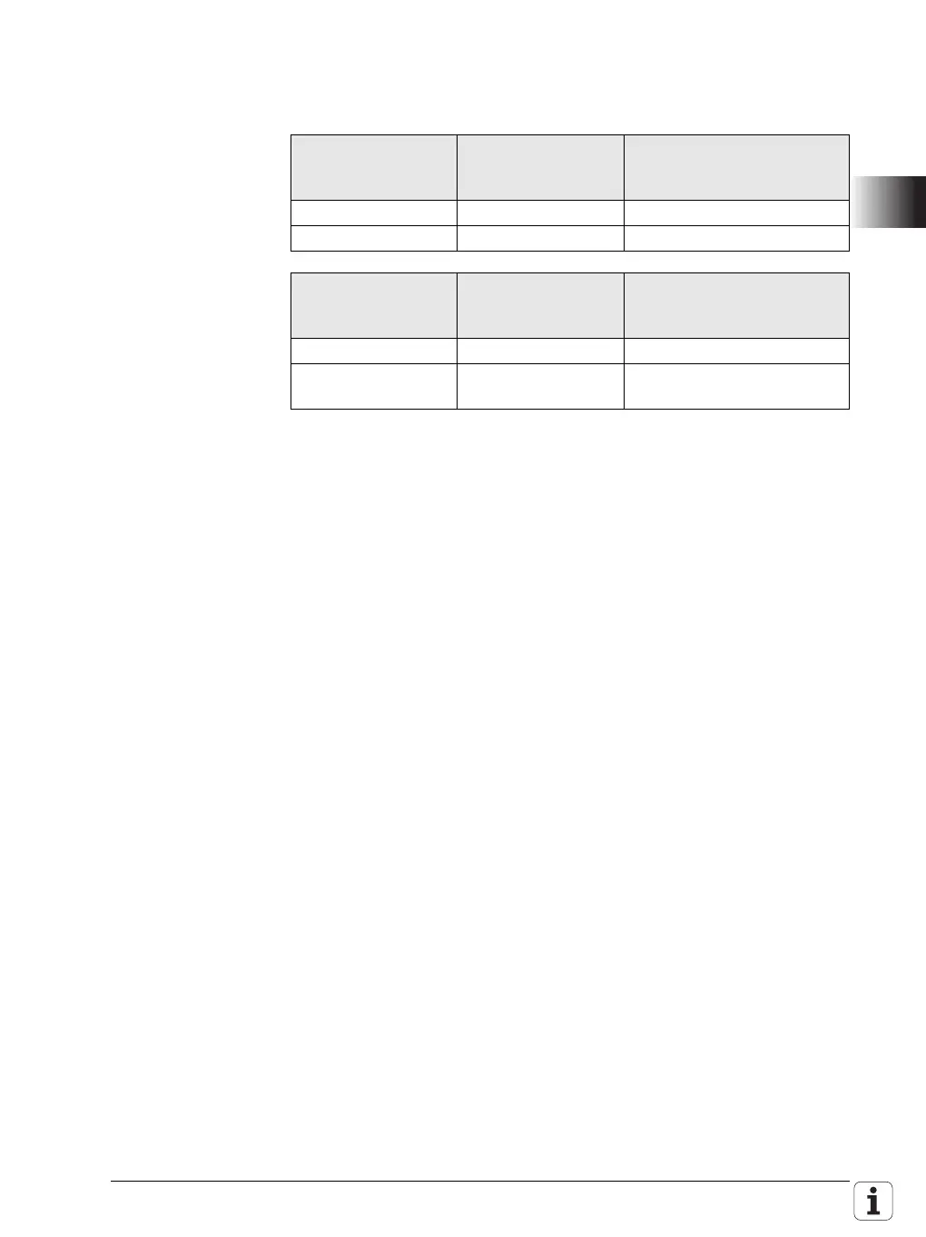
Voltage range PLD-H
(with LED)
UEC 11x, X9 of PL 62xx, and
machine operating panel
(without LED)
"1" signal: U
i
11 V to 30.0 V 11 V to 30.0 V
"0" signal: U
i
–3.0 V to 2.2 V –3 V to 2.2 V
Current range PLD-H
(with LED)
UEC 11x, X9 of PL 62xx, and
machine operating panel
(without LED)
"1" signal: I
i
2.0 mA to 6.1 mA 2.1 mA to 6.0 mA
"0" signal: I
i
at
U
i
= 2.2 V
0.3 mA 0.43 mA

 Loading...


