20
CONTROL COMMAND
20-15
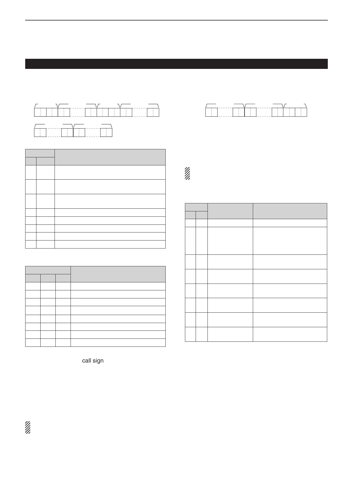
• DV RX call sign setting
Command : 20 0001, 20 0002
XX XXX XXX XX XX
……
!5–@2e–!0 !1–!4
XXXX
……
q、w
XX
……
XX
@3–#0
XX
……
X X
#1–#8
Header flag data (First byte) q
Data
Description
Bit
7
0
(fixed)
—
6
0
(fixed)
—
5
0
(fixed)
—
4 0/1 0= Voice, 1= Data
3 0/1 0= Direct, 1= Through repeater
2 0/1 0= No Break-in, 1= Break-in
1 0/1 0= Data, 1= Control
0 0/1 0= Normal, 1= Emergency
Header flag data (Second byte) w
Data
Function
Bit 2 Bit 1 Bit 0
1 1 1 Repeater control
1 1 0 Send auto acknowledge
1 0 1 (Not used)
1 0 0
Request to re-transmit
0 1 1 Send acknowledge
0 1 0 Receive no reply
0 0 1 Repeater disabled
0 0 0 NULL
e–!0 Caller station’s call sign (8 characters; fixed)
!1–!4 Caller station’s note (4 characters; fixed)
!5–@2 Called station’s call sign (8 characters; fixed)
@3–#0 Access repeater’s call sign (R1) (8 characters)
#1–#8 Gateway/Link repeater’s call sign (R2) (8 char-
acters; fixed)
See ‘Character code setting.’ (p. 20-12)
“FF” stands for no call sign receiving after turning ON
the transceiver.
• DV RX message setting
Command: 20 0101, 20 0102
XX XXXX XX
@1–@8 @9–#2
……
XX
……
XX
q–@0
q–@0 RX message (20 characters; fixed)
@1–@8 Call sign of the calling station (8 characters;
fixed)
@9–#2 Note of the calling station (4 characters; fixed)
See ‘Character code setting.’ (p. 20-12)
“FF” stands for no message receiving after turning
ON the transceiver.
• DV RX Status setting
Command: 20 0201, 20 0202
Data
Status Description
Bit
7 0 — —
6 0/1
Receiving a voice
call
During receiving a digital voice
signal, select “1.”
( Regardless of DSQL and
CSQL setting)
5 0/1
Last call finisher When the last call was fin-
ished by you, select “1.”
4 0/1
Receiving a sig-
nal
When the audio tone can be
heard, select “1.”
3 0/1
Receiving a BK
call
During receiving a BK call, se-
lect “1.”
2 0/1
Receiving a EMR
call
During receiving a EMR call,
select “1.”
1 0/1
Receiving a sig-
nal other than DV
When “DV” and “FM” are blink-
ing, select “1.”
0 0/1
Packet loss sta-
tus
During displaying a packet
loss
Data content description (Continued) D
Remote jack (CI-V) information

 Loading...


