2.6.4.6. 1G/10GbE PHY Interfaces
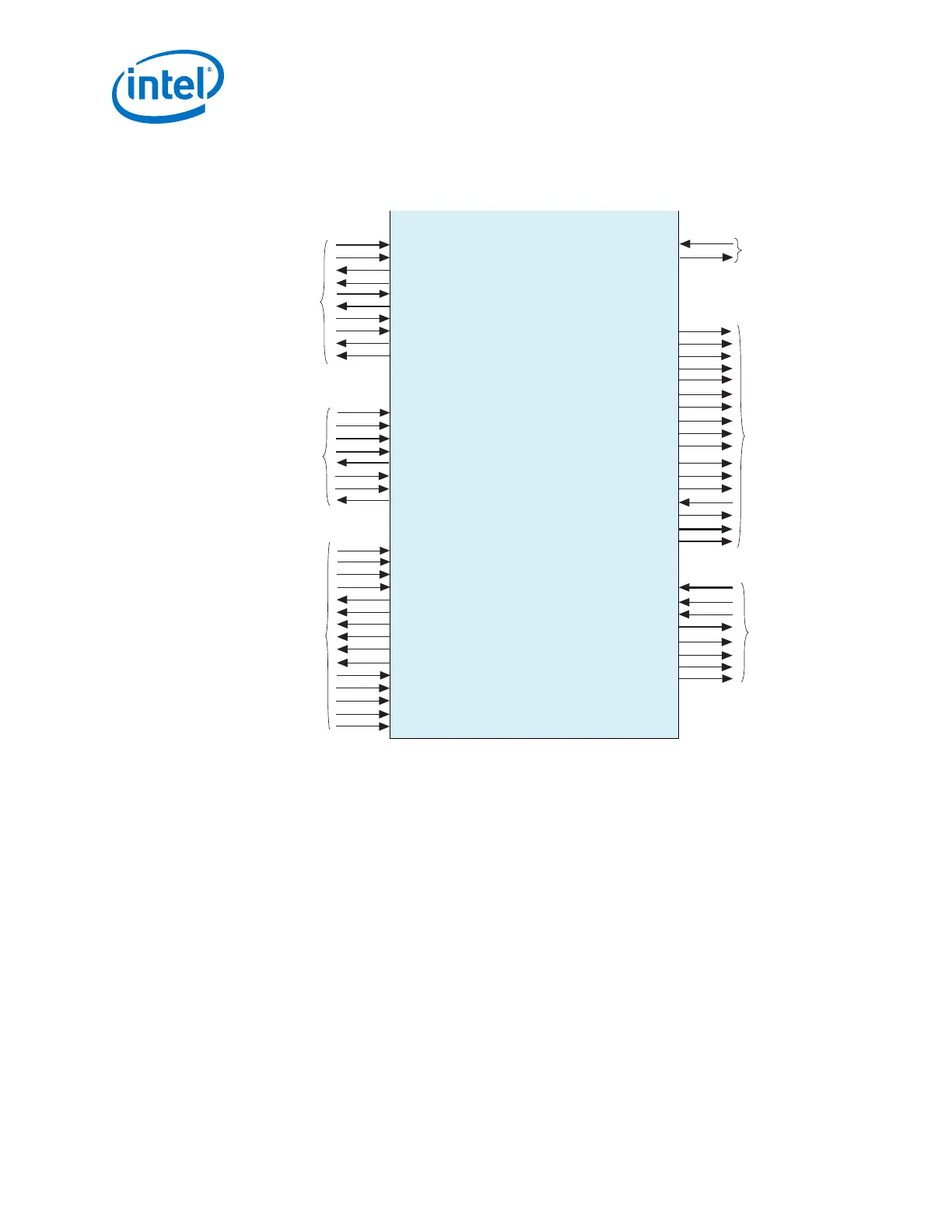
Figure 76. 1G/10GbE PHY Top-Level Signals
xgmii_tx_dc[71:0]
xgmii_tx_clk
xgmii_rx_dc[71:0]
xgmii_rx_clk
gmii_tx_d[7:0]
gmii_rx_d[7:0]
gmii_tx_en
gmii_tx_err
gmii_rx_err
gmii_rx_dv
led_char_err
led_link
led_disp_err
led_an
mgmt_clk
mgmt_clk_reset
mgmt_address[10:0]
mgmt_writedata[31:0]
mgmt_readdata[31:0]
mgmt_write
mgmt_read
mgmt_waitrequest
tx_serial_clk_10g
rx_cdr_ref_clk_10g
rx_cdr_ref_clk_1g
tx_pma_clkout
rx_pma_clkout
tx_clkout
rx_clkout
tx_pma_div_clkout
rx_pma_div_clkout
tx_analogreset
tx_digitalreset
rx_analogreset
rx_digitalreset
usr_seq_reset
1G/10GbE Top-Level Signals
rx_serial_data
tx_serial_data
rx_block_lock
rx_hi_ber
rx_is_lockedtodata
tx_cal_busy
rx_cal_busy
rx_syncstatus
tx_pcfifo_error_1g
rx_pcfifo_error_1g
rx_clkslip
rx_data_ready
Transceiver
Serial Data
XGMII
GMII
Interfaces
Avalon-MM PHY
Management
Interface
Clocks and
Reset
Interface
Status
tx_serial_clk_1g
rx_latency_adj_1g[21:0]
tx_latency_adj_1g[21:0]
led_panel_link
mii_tx_d[3:0]
mii_tx_en
mii_tx_err
mii_rx_d[3:0]
mii_rx_dv
mii_rx_err
mii_col
mii_crs
MII
Interfaces
The block diagram shown in the parameter editor labels the external pins with the
interface type and places the interface name inside the box. The interface type and
name are provided in the _hw.tcl file. If you turn on Show signals, the block
diagram displays all top-level signal names. For more information about _hw.tcl
files, refer to the Component Interface Tcl Reference chapter in volume 1 of the Intel
Quartus Prime Handbook.
Note: Intel is deprecating some of the signals shown in this figure. The descriptions of these
signals identifies them as not functional.
Related Information
Component Interface Tcl Reference
2. Implementing Protocols in Arria 10 Transceivers
UG-01143 | 2018.06.15
Intel
®
Arria
®
10 Transceiver PHY User Guide
174
 Loading...


