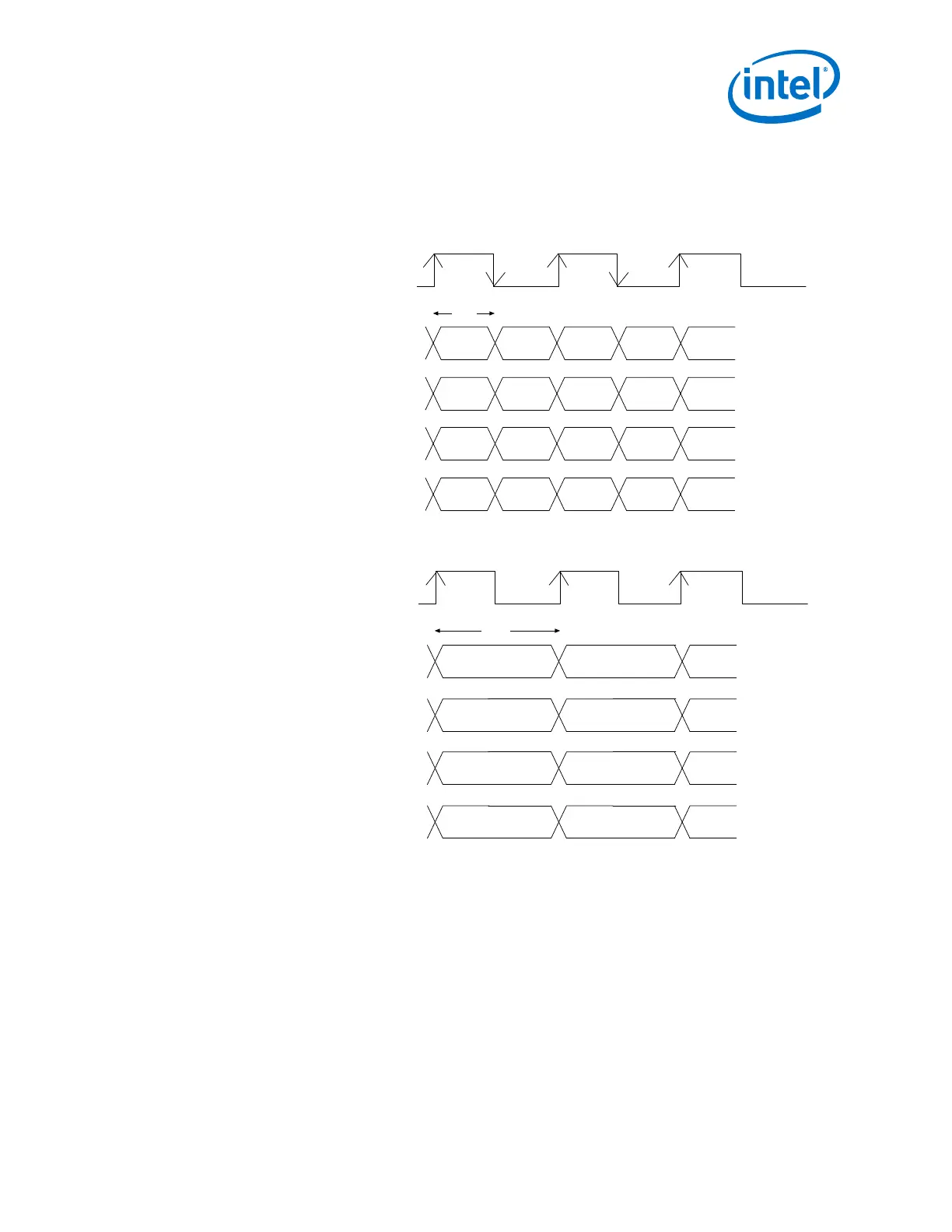
Figure 84. Implementation of the XGMII Specification in Arria 10 Devices Configuration
The ATX PLL is only supported to drive the internal transceiver. The FPLL is only supported to drive
xgmii_tx_clk and xgmii_rx_clk. Both the ATX PLL and the FPLL must be clocked by the same reference
clock to maintain 0 ppm.
Lane 0
Interface Clock (156.25 MHz)
8-bit
Interface Clock (156.25 MHz)
XGMII Transfer (DDR)
Lane 1
Lane 0
Lane 1
D0
{D1, D0} {D3, D2}
{D1, D0} {D3, D2}
Lane 2
Lane 3
{D1, D0} {D3, D2}
{D1, D0} {D3, D2}
D1 D2 D3
D0 D1 D2 D3
Lane 2
Lane 3
D0 D1 D2 D3
D0 D1 D2 D3
16-bit
Arria 10 Soft PCS Interface (SDR)
8B/10B Encoding/Decoding
Each of the four lanes in a XAUI configuration supports an independent 8B/10B
encoder/decoder as specified in Clause 48 of the IEEE802.3-2008 specification.
8B/10B encoding limits the maximum number of consecutive 1s and 0s in the serial
data stream to five. This limit ensures DC balance as well as enough transitions for the
receiver CDR to maintain a lock to the incoming data.
The XAUI PHY IP core provides status signals to indicate both running disparity and
the 8B/10B code group error.
2. Implementing Protocols in Arria 10 Transceivers
UG-01143 | 2018.06.15
Intel
®
Arria
®
10 Transceiver PHY User Guide
217
 Loading...


