5. Have a second person install a mounting screw—and cage nut and washer if your rack
requires them—in each of the four bracket holes to secure the device to the front rack
rails.
6. While still supporting the chassis, have the second person install a mounting
screw—and cage nut and washer if your rack requires them—in each of the four bracket
holes on the adjustable rear mounting brackets to secure the device to the rear rack
rails.
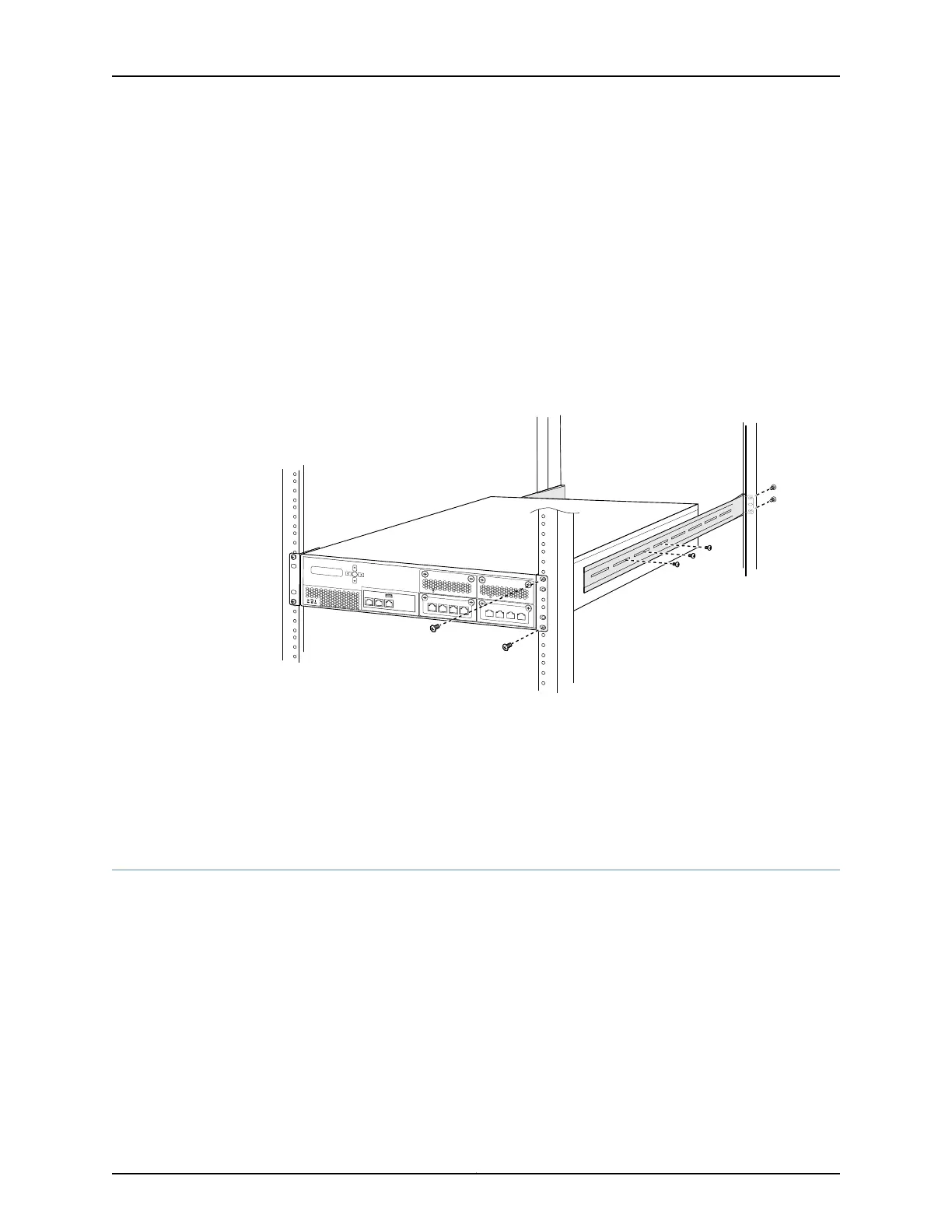
7. Ensure that the chassis is level by verifying that all the screws on the front of the rack
are aligned with the screws at the back of the rack. See Figure 58 on page 218.
Figure 58: Mounting a QFX3100 Director Device on Four Posts in a Rack
or Cabinet
Related
Documentation
Connecting Earth Ground to an EX Series Switch•
• Connecting AC Power to a QFX3100 Director Device on page 218
• Installing and Connecting a QFX3100 Director Device on page 213
• Rack-Mounting and Cabinet-Mounting Warnings on page 179
Connecting AC Power to a QFX3100 Director Device
The power supply in a QFX3100 Director device is a hot-removable and hot-insertable
field-replaceable unit (FRU) located on the far right side of the rear panel. You can remove
and replace a single power supply without powering off the QFX3100 Director device or
disrupting QFX3100 Director device functions.
Before you begin connecting AC power to a QFX3100 Director device:
Copyright © 2012, Juniper Networks, Inc.218
QFX3000 Hardware Documentation