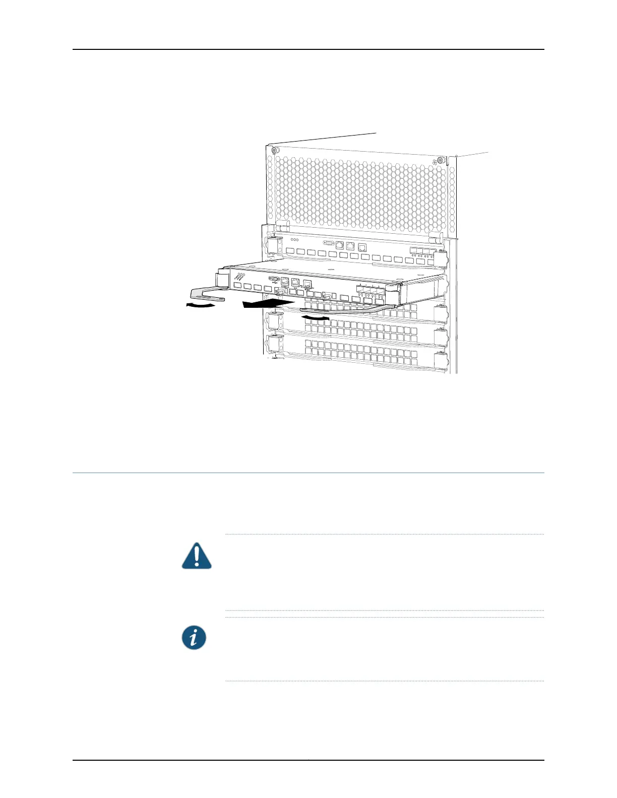
Figure 112: Removing a Control Board from a QFX3008-I Interconnect
Device
Related
Documentation
Installing a Control Board in a QFX3008-I Interconnect Device on page 349•
• Control Board in a QFX3008-I Interconnect Device on page 49
• Control Board LEDs on a QFX3008-I Interconnect Device on page 389
Installing a Control Board in a QFX3008-I Interconnect Device
There are two Control Boards in a QFX3008-I Interconnect device. The Control Boards
install horizontally in the rear of the chassis in the slots labeled CB 0 and CB 1. See “Slot
Numbering for a QFX3008-I Interconnect Device” on page 40.
CAUTION: Do not lift modules by holding the ejector levers. The levers cannot
support the weight of the module. Lifting the module by the levers might
bend the levers, and the bent levers prevent the board from being properly
seated in the chassis.
NOTE: When you install a new Control Board in the QFX3008-I Interconnect
device, the Junos OS is updated to the same version that is running on the
QFX3100 Director group.
349Copyright © 2012, Juniper Networks, Inc.
Chapter 26: Replacing QFX3008-I Components