CHAPTER 22
Cabling the QFabric Switch
•
Interconnecting Two Virtual Chassis for QFabric System Control Plane
Redundancy on page 271
•
Connecting QFX3100 Director Devices in a Director Group on page 274
•
Connecting QFX3100 Director Devices to the Control Plane Network on page 275
•
Connecting a QFX3100 Director Device to a Network for Out-of-Band
Management on page 277
•
Connecting a QFX3008-I Interconnect Device to the Control Plane Network on page 278
•
Connecting a QFX3500 Node Device to the Control Plane Network on page 282
•
Connecting a QFX3500 Node Device to a QFX3008-I Interconnect Device on page 284
•
Connecting a QFX Series Device to a Management Console on page 285
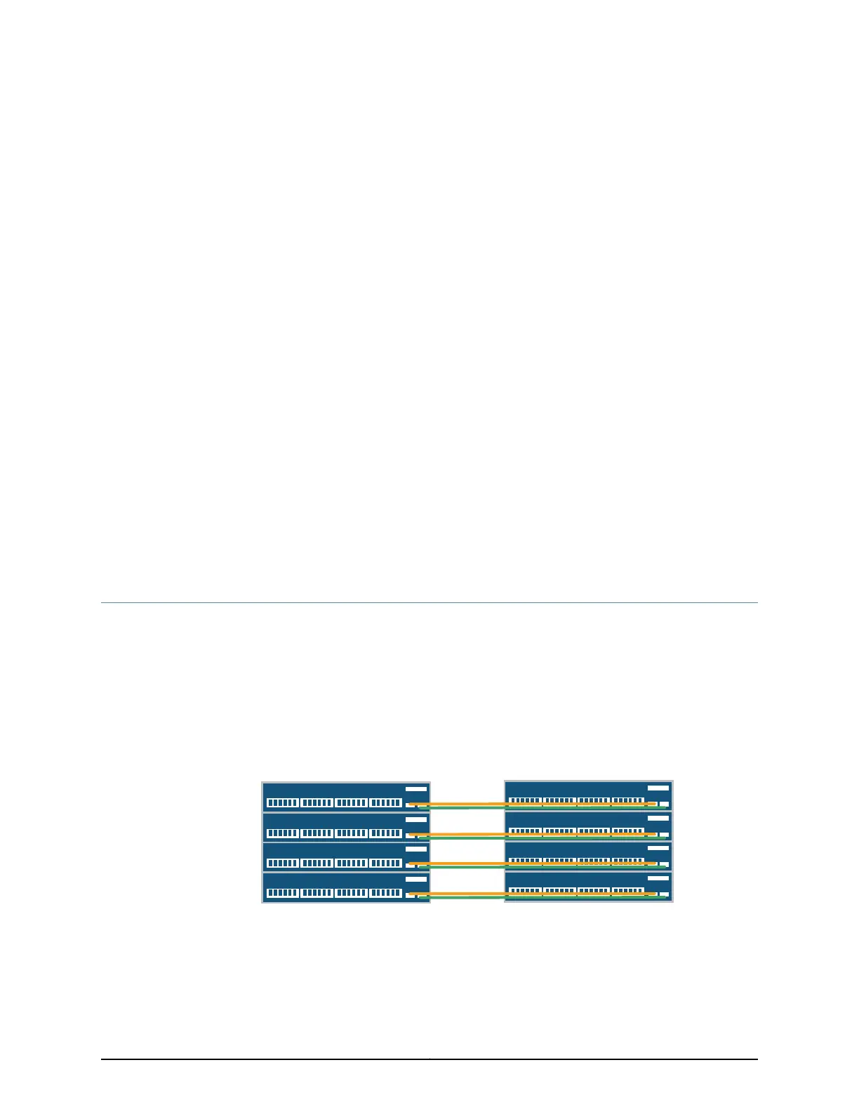
Interconnecting Two Virtual Chassis for QFabric System Control Plane Redundancy
A QFX3000 QFabric system control plane and management network is formed by
connecting the QFX series devices in your network to two Virtual Chassis composed of
four EX4200 switches each. For redundancy and communication, you must connect the
two Virtual Chassis using the 10-Gigabit Ethernet uplink module ports configured as a
link aggregation group (LAG) (see Figure 80 on page 271).
Figure 80: QFabric System Control Plane—Inter-Virtual Chassis LAG
Connections
VC0
VC1
xe-1/1/0
xe-2/1/0
xe-3/1/0
xe-0/1/0
xe-1/1/0
xe-2/1/0
xe-3/1/0
xe-0/1/0
xe-1/1/2
xe-2/1/2
xe-3/1/2
xe-0/1/2
xe-1/1/2
xe-2/1/2
xe-3/1/2
xe-0/1/2
g041163
Before you begin to interconnect two Virtual Chassis for QFabric system control plane
redundancy:
271Copyright © 2012, Juniper Networks, Inc.