6. Place the front card in the antistatic bag or on the antistatic mat.
7. If you are not replacing the front card, install the cover panel over the empty slot by
rotating the knob on the top and bottom of the cover panel to the closed position.
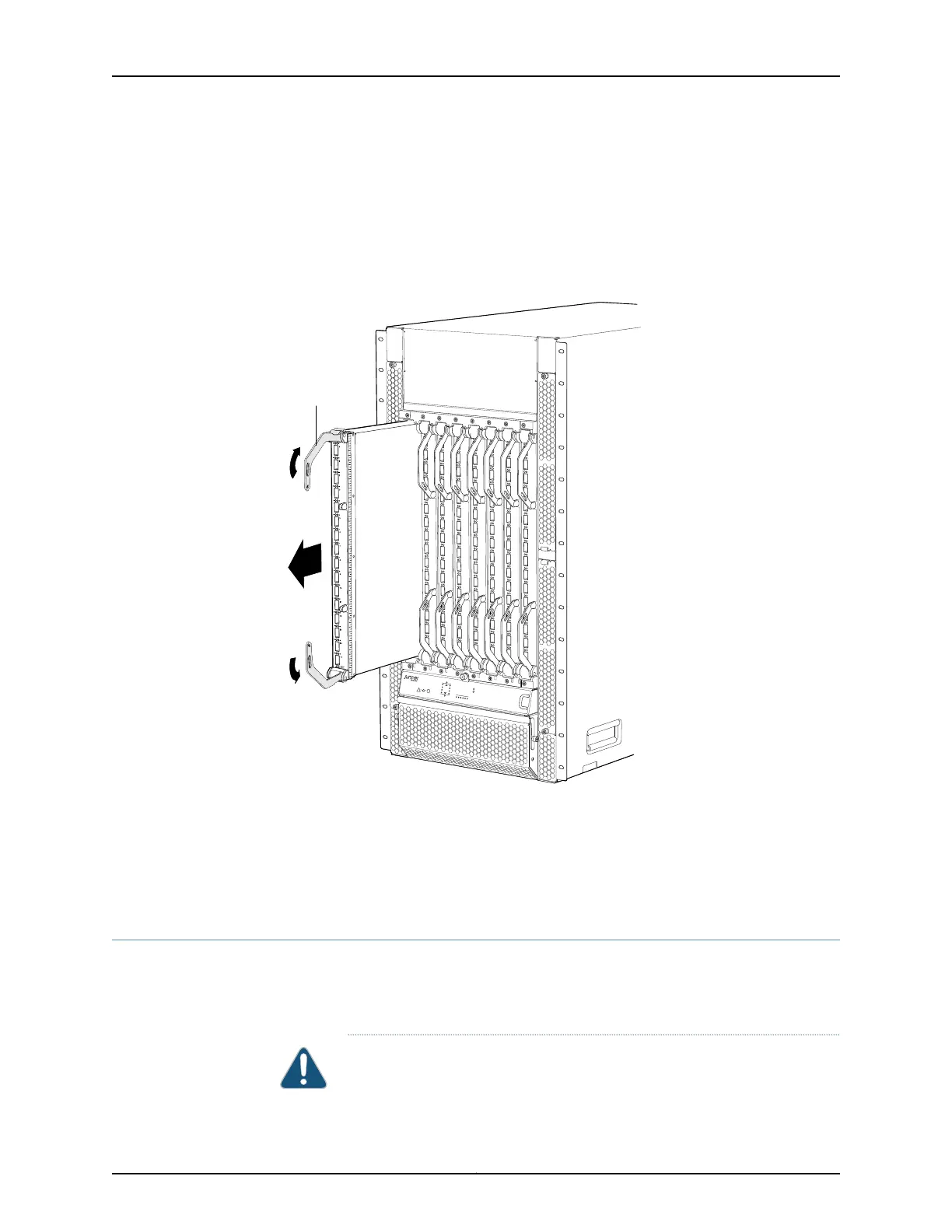
Figure 114: Removing a 16-Port Front Card from a QFX3008-I Interconnect
Device
FXIC08
g050139
Ejector
lever
Related
Documentation
Installing a 16-PortQSFP+ Front Card in a QFX3008-I Interconnect Device on page 353•
• 16-Port QSFP+ Front Cards in a QFX3008-I Interconnect Device on page 48
• 16-Port QSFP+ Front Card LEDs on a QFX3008-I Interconnect Device on page 391
Installing a 16-Port QSFP+ Front Card in a QFX3008-I Interconnect Device
You can install up to eight 16-port QSFP+ front cards in a QFX3008-I Interconnect device.
The front cards are installed vertically in the front of the chassis in the slots labeled 0
through 7. See “Slot Numbering for a QFX3008-I Interconnect Device” on page 40.
CAUTION: Do not lift modules by holding the ejector levers. The levers cannot
support the weight of the module. Lifting the module by the levers might
353Copyright © 2012, Juniper Networks, Inc.
Chapter 26: Replacing QFX3008-I Components