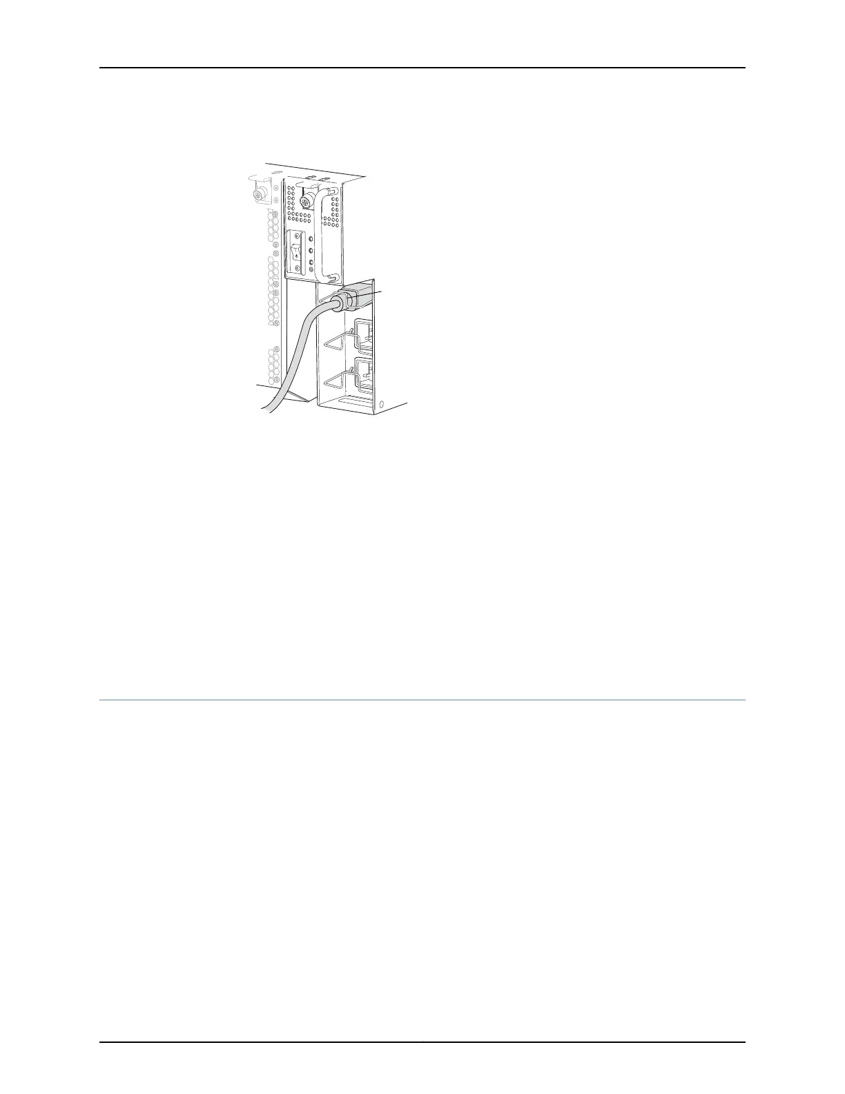
Figure 64: Connecting an AC Power Cord to a Single-Phase Wiring Tray
PHASE 3
3
2
1
PHASE 2
PHASE 1
g050112
Cord
retainer
6. If the AC power source outlet has a power device, set it to the OFF (0) position.
7. Insert the power cord plug into an AC power source outlet.
8. Repeat Step 5 through Step 7 for each AC appliance inlet on the wiring tray faceplate.
9. If the AC power source outlet has a power device, set it to the ON (|) position.
10. Verify that each LED on the wiring tray faceplate is lit solid green. Verify that each LED
on the power supply faceplate is lit solid green.
Related
Documentation
Powering On a QFX3008-I Interconnect Device on page 253•
• Wiring Tray in a QFX3008-I Interconnect Device on page 54
• Wiring Tray LEDs on a QFX3008-I Interconnect Device on page 395
Preparing Delta and Wye Three-Phase Power Cords
A QFX3008-I Interconnect device can be configured with two three-phase wiring trays.
Delta and wye wiring configurations are available. A licensed electrician must prepare
the power cords that you provide for installation in the wiring tray. Several parts included
with the wiring trays enable the power cords to be dressed in different positions. If you
need the power cable to be routed up to the top of a rack, you must use the included 90°
connector to enable the power cord to be routed upward (see Figure 65 on page 242).
The 90° connector provides more flexibility to position the power cord outside the width
of the chassis. Alternatively, if the power cords will be routed down to the bottom of the
rack, or space limitations prevent you from extending the width of the chassis footprint,
you can use the flat connector to install the power cord (see Figure 66 on page 242). Figure
67 on page 243 and Figure 68 on page 243 show the power cords installed on the wiring
trays in the two different positions. Figure 69 on page 244 shows the wiring tray being
installed in the chassis, using the flat connector.
241Copyright © 2012, Juniper Networks, Inc.
Chapter 19: Installing a QFX3008-I Interconnect Device