Each power supply is cooled by its own fans. The airflow is from the front of the power
supply to the back. Hot air exhausts from the rear of the chassis. Three LEDs on the
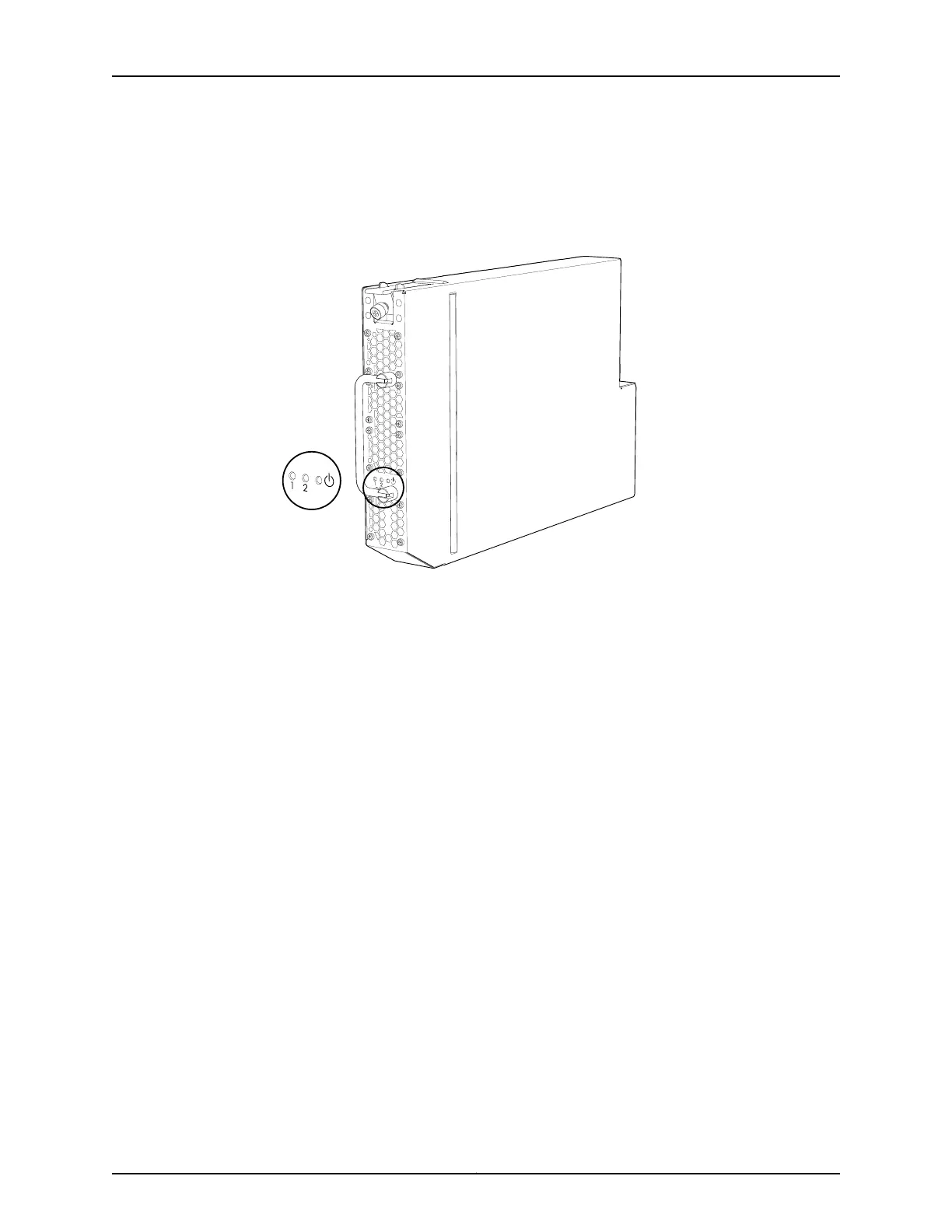
faceplate indicate the status of the power supply. See Figure 27 on page 53.
Figure 27: AC Power Supply
Each power supply contains two isolated 2000-W channels that produce 54 VDC. The
midplane distributes the output power produced by the power supplies to different
system components.
The distribution of power to the QFX3008-I Interconnect device is divided between
components, and each power supply provides power to different components. Together,
the three power supplies in slots 0 through 2 provide power for the entire system. Likewise,
the power supplies in slots 3 through 5 also provide power to the entire system. In standard
power redundancy terminology, the two sets of three power supplies provide 2N
redundancy for the QFX3008-I Interconnect device, where N is the number of power
supplies.
Because each power supply provides power to a subset of components, a second power
supply that provides power to the same components must be installed for redundancy.
For example, during normal operation the power supplies in slot 1 and slot 4 provide
power to the same components on a load-sharing basis. If the power supply in slot 1 fails,
the power supply in slot 4 can provide full power to the components indefinitely.
Table 8 on page 54 lists the pairs of power supplies and the components they power in
a QFX3008-I Interconnect device.
53Copyright © 2012, Juniper Networks, Inc.
Chapter 3: QFX3008-I Overview