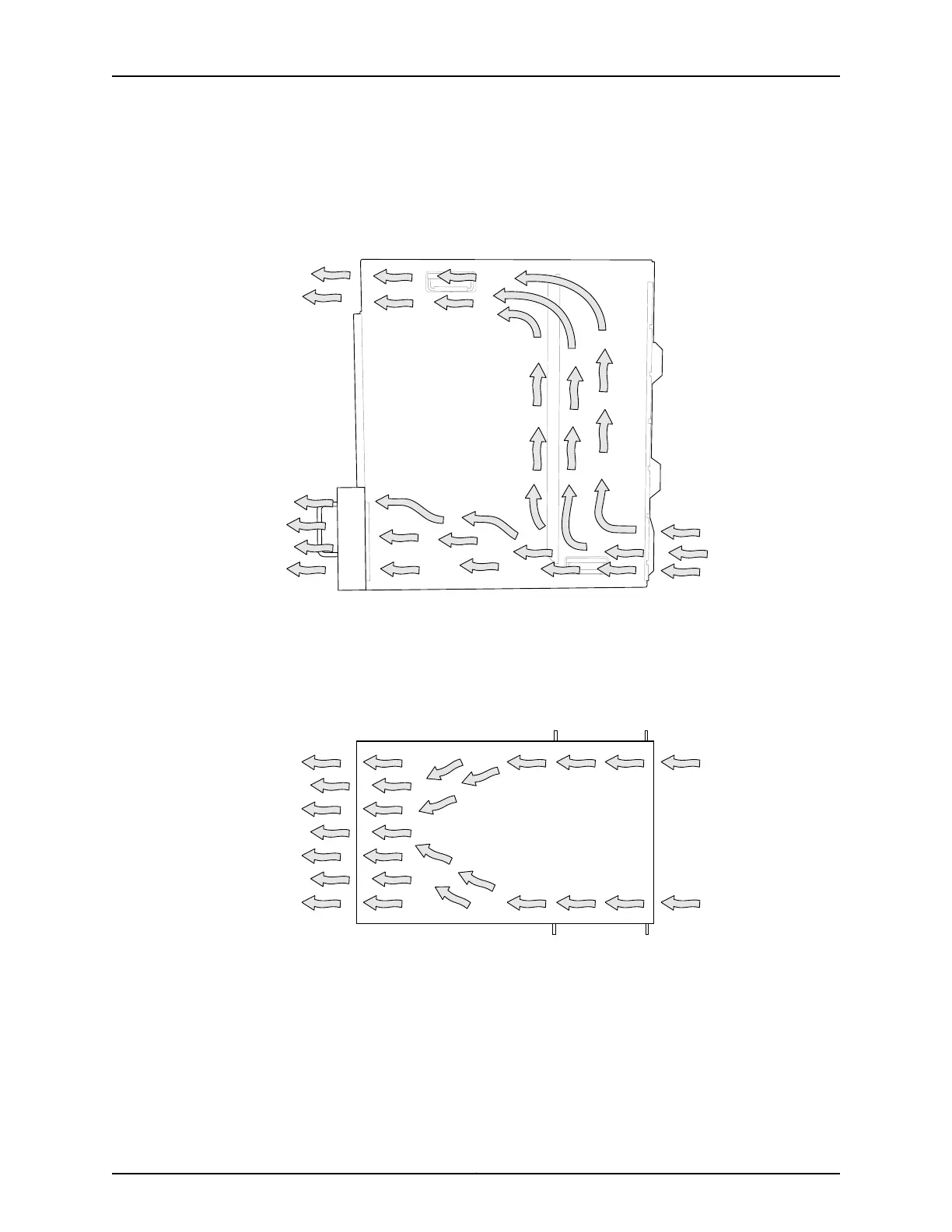
The air intake to cool the front card cage and powerhouse is located below the front
fan tray on the chassis. Hot air exhausts from the powerhouse at the bottom of the
chassis, and above the rear fan tray at the top of the chassis.
Figure 49: Airflow Through the Front Card Cage and Powerhouse
g050103
Front
Side view
Rear
The air intake to cool the rear card cage is located on the front sides of the chassis.
Cool air is pulled in through the side fan trays. Hot air exhausts from the Control Boards
and rear cards.
Figure 50: Airflow Through the Rear Card Cage
•
If you are mounting the device on a rack or cabinet along with other equipment, ensure
that the exhaust from other equipment does not blow into the intake vents of the
chassis.
•
Leave at least 24 in. (61 cm) both in front of and behind the switch. Allow at least 6 in.
(15.2 cm) of clearance on each side of the chassis. Leave adequate space at the front
of the switch for service personnel to remove and install hardware components. NEBS
101Copyright © 2012, Juniper Networks, Inc.
Chapter 6: Rack and Cabinet Requirements