Before you begin installing an HDD module in a QFX3100 Director device:
•
Ensure that you understand how to prevent electrostatic discharge (ESD) damage.
See “Prevention of Electrostatic Discharge Damage” on page 192.
Ensure that you have the following parts and tools available:
•
ESD grounding strap
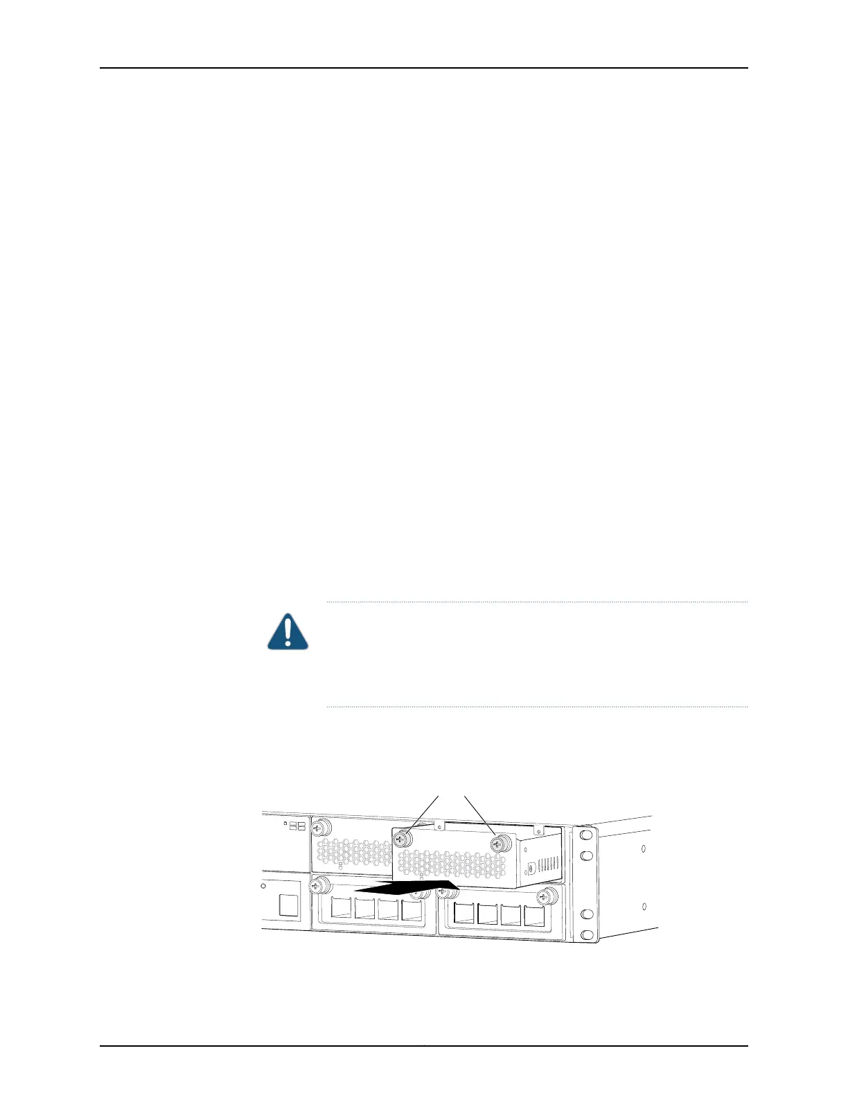
To install an HDD module in a QFX3100 Director device (see Figure 95 on page 319):
1. Attach the ESD grounding strap to your bare wrist, and connect the strap to a site ESD
point.
2. Taking care not to touch HDD module components, pins, leads, or solder connections,
remove the HDD module from its bag.
3. If the Director device is powered on, at least one HDD module must be installed at all
times. You should only perform this step when an HDD module in the other HDD slot
is installed and operational.
If an HDD module in the HDD module slot needs to be removed, remove the HDD
module. See “Removing an HDD Module from a QFX3100 Director Device” on page 317
4. Ensure that the HDD module is properly aligned with the HDD module slot. The HDD
module faceplate should be aligned so the screws are aligned with the top of the HDD
module slot.
5. Insert the HDD module into the HDD module slot, and gently push the module all the
way into the slot until the module is seated flush in the HDD module slot.
CAUTION: If backpressure prevents the HDD module from seating flush
in the HDD module slot, remove the HDD module from the slot and retry
the procedure, taking care to ensure that the HDD module is properly
aligned with the HDD module slot.
6. Tighten both screws on the HDD module, using your fingers.
Figure 95: Installing an HDD Module in a QFX3100 Director Device
Slot
0
1
1
2
g050063
Slot
0
1
1
2
g050054
Slot
0
1
1
2
g050065
Loosen captive screws.
Tighten captive screws.
Slot
0
1
1
2
g050056
Tighten captive screws.
g050054
Slot
0
1
1
2
g050065
Loosen captive screws.
Tighten captive screws.
Slot
0
1
1
2
g050056
Tighten captive screws.
Tighten captive screws.
319Copyright © 2012, Juniper Networks, Inc.
Chapter 25: Replacing QFX3100 Components