CAUTION: You must power off the QFX3500 device before replacing the
management board.
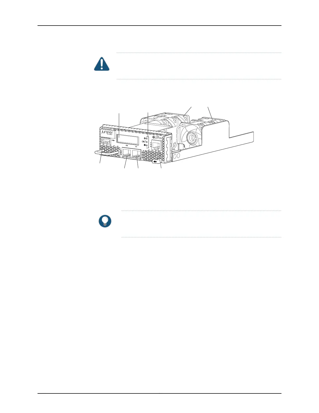
Figure 42 on page 72 shows the management board.
Figure 42: Management Board for a QFX3500 Device
g050021
Management
ports
USB
port
Console
port
Fan modules
Chassis
status LEDs
LCD display
QFX3500-48S4Q
The management board contains the following components on the faceplate:
•
LCD panel—The LCD panel displays the device hostname and the number of active
alarms.
TIP: Alternatively, you can use the show chassis lcd CLI command to view
what is currently displayed on the LCD panel.
•
Chassis status LEDs
•
USB port
•
Console (CON) port (RJ-45)
•
Management (C0 and C1) ports
There are two types of management boards:
•
RJ-45 management board—Provides two 1000BASE-T RJ-45 management ports.
•
If you are using the QFX3500 deviceas a Node device in a QFabricsystem,see “Cable
Specifications for Control Plane Connections for the QFX Series” on page 129 for
information about the required cables.
•
If you are using the QFX3500 device as a standalone switch, see “Cable Specifications
for Console and Management Connections for the QFX Series” on page 130 for
information about the required cables.
•
SFP management board—Provides two 1-Gbps small form-factor pluggable (SFP)
management ports.
Copyright © 2012, Juniper Networks, Inc.72
QFX3000 Hardware Documentation