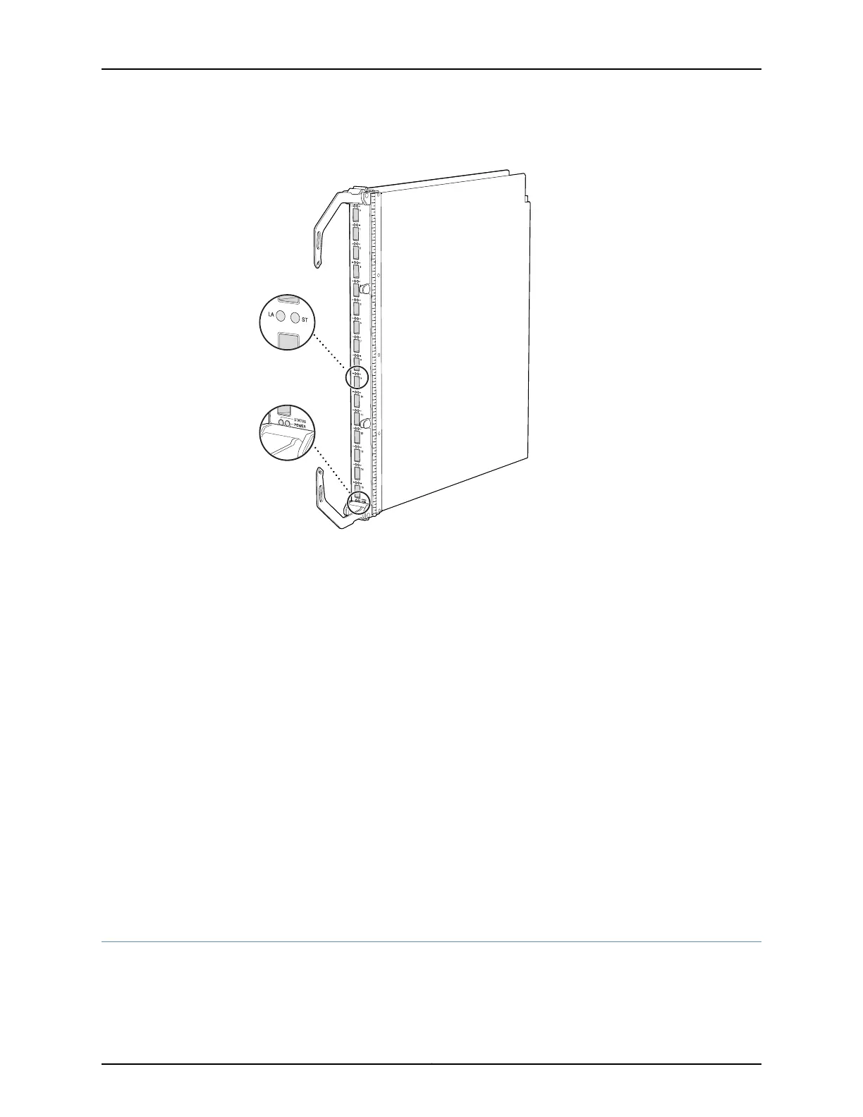
Figure 24: 16-Port QSFP+ Front Card
g050153
Link/Activity
and Status LEDs
Front card
status LEDs
The 16-port QSFP+ front cards are installed in the front of the chassis in the slots labeled
0 through 7. See “Slot Numbering for a QFX3008-I Interconnect Device” on page 40.
The 16-port QSFP+ front cards are hot-insertable and hot-removable field-replaceable
units (FRUs). However, you must take the front cards offline before removing them. See
“Taking a 16-Port QSFP+ Front Card Offline in a QFX3008-I Interconnect Device” on
page 351.
Each 16-port QSFP+ front card has these components:
•
LEDs—Indicate port and system status. See “16-Port QSFP+ Front Card LEDs on a
QFX3008-I Interconnect Device” on page 391.
•
16 40-Gbps QSFP+ ports—Connect to the QFX3500 Node devices in your QFX3000
QFabric system for data path connectivity.
•
Ejector levers—Used for installing and removing the front card.
Related
Documentation
Removing a 16-Port QSFP+ Front Card from a QFX3008-I Interconnect Device on
page 352
•
• Installing a 16-Port QSFP+ Front Card in a QFX3008-I Interconnect Deviceon page 353
Control Board in a QFX3008-I Interconnect Device
The Control Board performs Routing Engine functions in a QFX3008 Interconnect device.
See Figure 25 on page 50.
49Copyright © 2012, Juniper Networks, Inc.
Chapter 3: QFX3008-I Overview