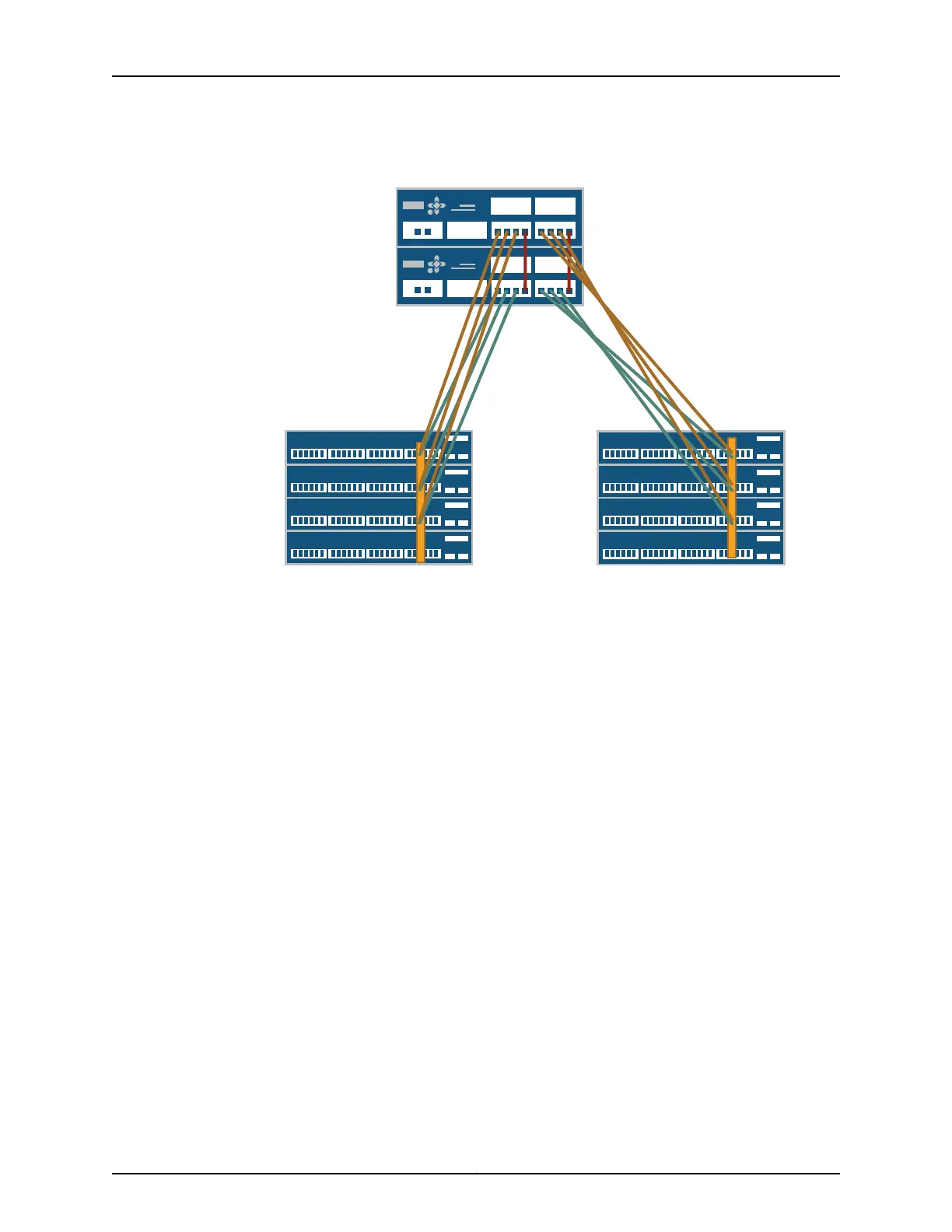
Figure 83: QFX3100 Director Group to Virtual Chassis Connections
VC0
VC1
DG0
DG1
0
1 2 3
0
1 2 3
To port 40 To port 41
To port 41
To port 40
0
1 2 3
Patch cables
between Director devices
0
1 2 3
g041124
Specific ports have been reserved on the Virtual Chassis to connect to each of the QFabric
system device types. Such design simplifies installation and facilitates timely deployment
of a QFabric system. It also permits the use of a standard Virtual Chassis configuration
(see Example: Configuring the Virtual Chassis for the QFabric Switch Control Plane).
Before you begin to connect a QFX3100 Director device to the control plane network:
•
Install your QFabric system hardware (Director group, Interconnect devices, and Node
devices). See “Installing and Connecting a QFX3100 Director Device” on page 213,
“Installing and Connecting a QFX3008-I Interconnect Device” on page 223, and “Installing
and Connecting a QFX3500 Device” on page 259.
•
Install your Virtual Chassis hardware (EX4200 switches). See Installing and Connecting
an EX4200 Switch.
•
Create two Virtual Chassisswitches of four members each. See Configuring an EX4200
or EX4500 Virtual Chassis (CLI Procedure).
•
Interconnect the two Virtual Chassis switches using the 10-Gigabit Ethernet SFP+
uplink ports. See “Interconnecting Two Virtual Chassis for QFabric System Control
Plane Redundancy” on page 271.
•
Connect the two QFX3100 Director devices to create a Director group. See “Connecting
QFX3100 Director Devices in a Director Group” on page 274.
•
Ensure that you have 12 RJ-45 patch cables available. For cable specifications, see
“Cable Specifications for Control Plane Connections for the QFX Series” on page 129.
Copyright © 2012, Juniper Networks, Inc.276
QFX3000 Hardware Documentation