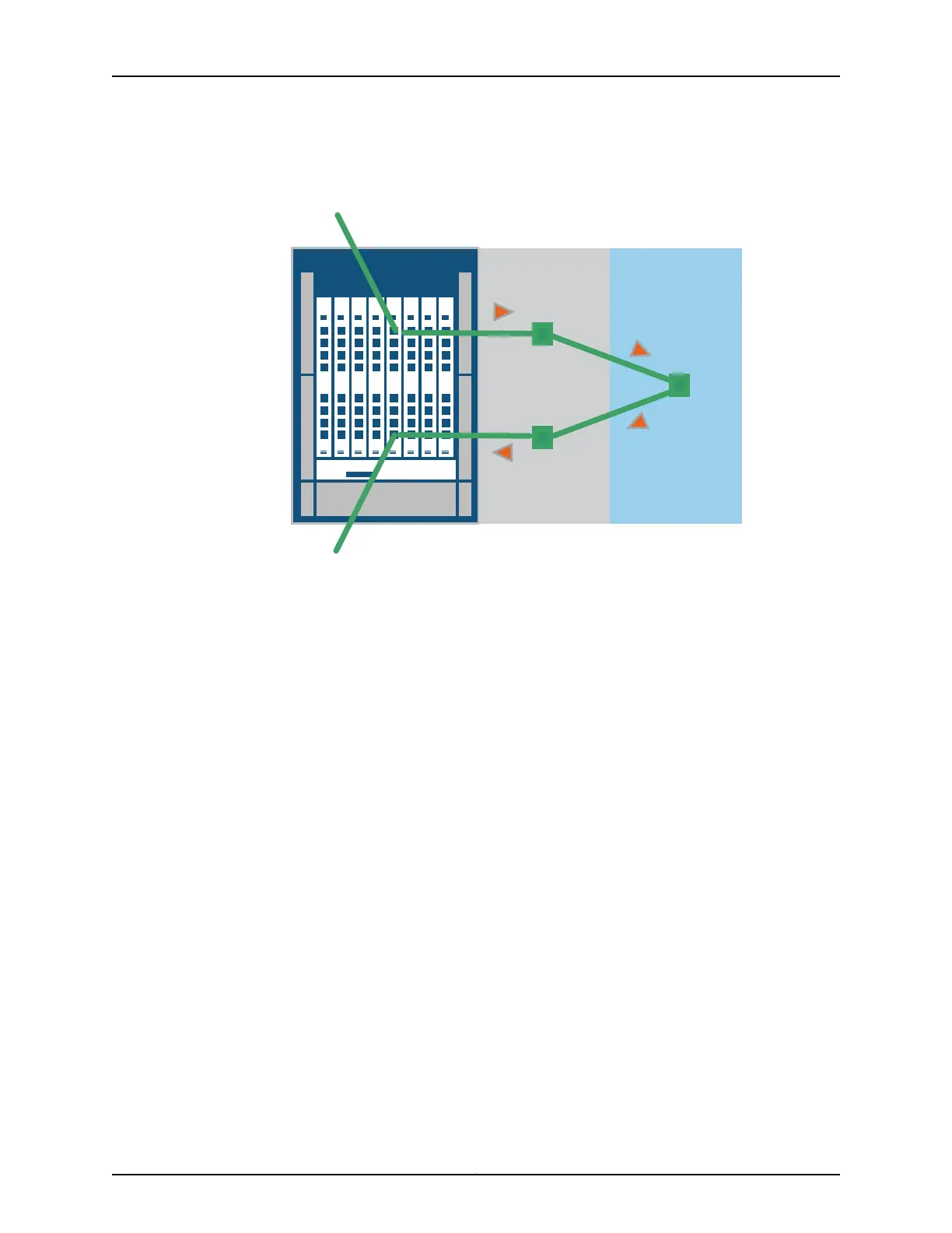
Figure 5: Clos Switching for Interconnect Devices
IC0
F1
Incoming traffic
Outgoing traffic
Front Card Rear Card
F3
F2
g041161
Traffic enters a QSFP+ port from a Node device, and an ingress chipset provides stage
F1 processing. For the F2 stage, the frame is sent to a rear card and processed by a
midplane chipset. Lastly, an egress chipset on the front card QSFP+ port handles
processing tasks for the F3 stage. At each of the three Clos stages, a switching table
chooses the best path and determines where to send the frame to reach the next stage.
The F1 and F3 stages can be handled by the same front card or different front cards,
depending on the best path selected by the fabric. After the frame traverses the
Interconnect backplane, the Interconnect device sends the frame to the egress Node
device.
QFX3008-I Interconnect Devices
The QFX3008-I Interconnect device contains eight slots in the front of the chassis. In
each slot, you can install a front card containing 16 40-Gbps quad, small-form factor
pluggable plus (QSFP+) ports. A fully configured system offers a total capacity of 128
QSFP+ connections. These front card ports attach to the high-speed backplane to reach
the eight slots in the rear of the chassis, which provide the heavy-duty interconnections
for the entire QFabric system. In addition, four interfaces (two per Control Board) provide
Gigabit Ethernet access to the control plane management network. Figure 6 on page 16
shows an example of the data plane and control plane connections for a QFX3008-I
Interconnect device.
15Copyright © 2012, Juniper Networks, Inc.
Chapter 1: QFX3000 QFabric Switch Overview