EasyManuals Logo

Juniper QFX Series User Manual

Juniper QFX Series
472 pages
To Next Page IconTo Next Page
To Previous Page IconTo Previous Page
Page #73 background imageLoading...
Page #73 background image
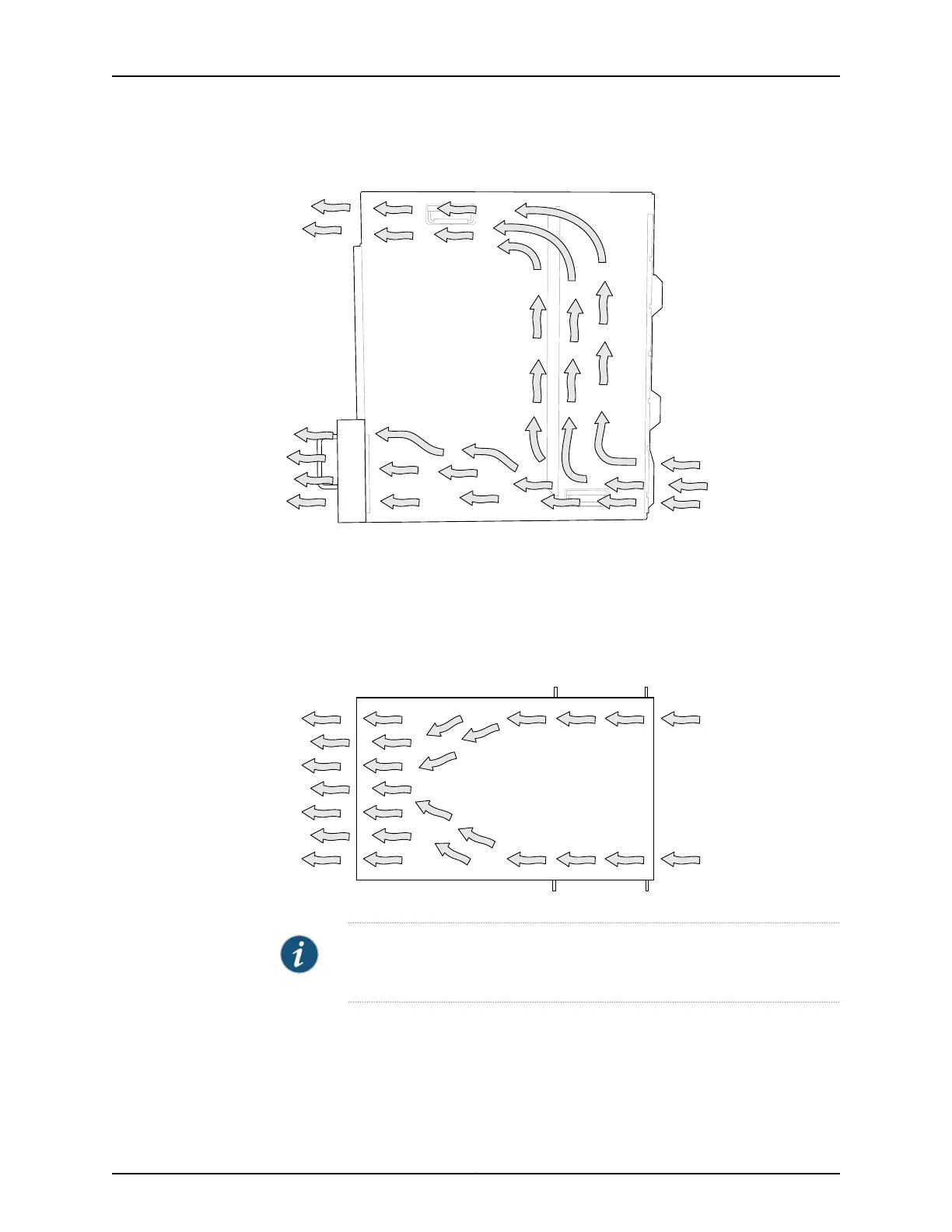
Figure 22: Airflow Through the Front Card Cage and Powerhouse
g050103
Front
Side view
Rear
Cooling for the rear card cage is also front to back. The air intake to cool the rear card
cage is located on the front sides of the chassis. Cool air is pulled in through the side fan
trays. The hot air exhausts through the rear card cage. See Figure 23 on page 47 for this
airflow.
Figure 23: Airflow Through the Rear Card Cage
Top view
Front
Rear
g050102
NOTE: Do not block the air intake at the bottom front of the chassis, or the
side fan trays.
The Control Board monitors the temperature of device components. Under normal
operating conditions, the fans in the fan trays run at less than full speed.
If the chassis temperature rises above the acceptable threshold the speed of the working
fans is automatically adjusted to keep the temperature within the acceptable range. If
47Copyright © 2012, Juniper Networks, Inc.
Chapter 3: QFX3008-I Overview

Table of Contents

Other manuals for Juniper QFX Series

Questions and Answers:

Question and Answer IconNeed help?

Do you have a question about the Juniper QFX Series and is the answer not in the manual?

Juniper QFX Series Specifications

General IconGeneral
CategorySwitch
SeriesQFX
Form Factor1U, 2U, and modular chassis options
Power SupplyRedundant, hot-swappable power supplies
Coolinghot-swappable fans
Virtual ChassisSupported on certain models
Typical UseData center, cloud
Operating SystemJunos OS
ManagementCLI
Key FeaturesHigh performance, low latency, automation
LatencySub-microsecond latency
Port DensityVaries by model (e.g., QFX5100: up to 48x10GbE + 6x40GbE)

Related product manuals