•
Control Board LEDs—Indicate system status. See “Control Board LEDs on a QFX3008-I
Interconnect Device” on page 389.
•
USB port—Provides an interfacethrough which you can recover the device by reinstalling
Junos OS software. See “USB Port Specifications for the QFX Series” on page 105 and
“Performing a Recovery Installation on a QFX3500 Device and QFX3008-I Interconnect
Device” on page 409.
•
Console port—Connects the Control Board to a management console through a serial
connection using a cable with an RJ-45 connector. See “Connecting a QFX Series Device
to a Management Console” on page 285.
•
Auxiliary port—This port is not enabled. It is reserved for future use.
•
Management port—This port is not enabled. It is reserved for future use.
•
Four Gigabit Ethernet SFP+ ports—Connect the Control Board to the QFX3000-G
QFabric system control plane network. See “Connecting a QFX3008-I Interconnect
Device to the Control Plane Network” on page 278.
•
Ejector levers—Used for installing and removing the Control Board.
Related
Documentation
Installing a Control Board in a QFX3008-I Interconnect Device on page 349•
• Removing a Control Board from a QFX3008-I Interconnect Device on page 347
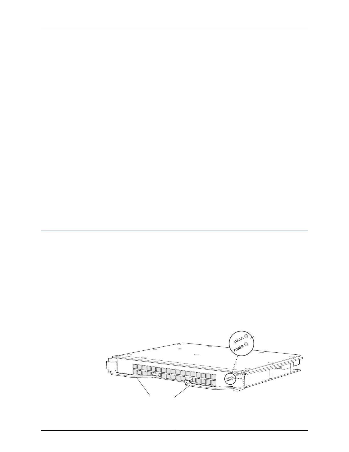
Rear Cards in a QFX3008-I Interconnect Device
The rearcards providethe intermediate stage of switch fabric functionality in a QFX3008-I
Interconnect Device. See Figure 26 on page 51.
A QFX3008-I Interconnect Device has eight rear cards. In the QFX3008-I Interconnect
Device, all eight rear cards are simultaneously active when the device is operational. All
rear cards are fully connected to all installed 16-port QSFP+ front cards. If a single rear
card fails, the input/output traffic for that card is load-balanced among the remaining
rear cards, providing graceful degradation in switching performance. The impact of a rear
card failure on the performance of a QFX3008-I Interconnect Device varies based on the
number of 16-port QSFP+ front cards installed in the device and the traffic mix flowing
through them.
Figure 26: Rear Card in a QFX3008-I Interconnect Device
g050157
Rear card status LEDs
Ejector levers
51Copyright © 2012, Juniper Networks, Inc.
Chapter 3: QFX3008-I Overview