Table 68: Link/Activity LED on the Management Port on a QFX3100 Director Device
DescriptionStateColorLED
There is no link established.OffUnlitLink/Activity
A link is established, but there is no activity on the
link.
On steadilyGreen
There is link activity.Flickering
10-Mbps link is established. However, if the
Link/Activity LED is also unlit, this indicates there
is no link established.
OffUnlitSpeed
100-Mbps link is established.On steadilyGreen
1-Gbps link is established.On steadilyAmber
Related
Documentation
Front Panel of a QFX3100 Director Device on page 26•
• Installing and Connecting a QFX3100 Director Device on page 213
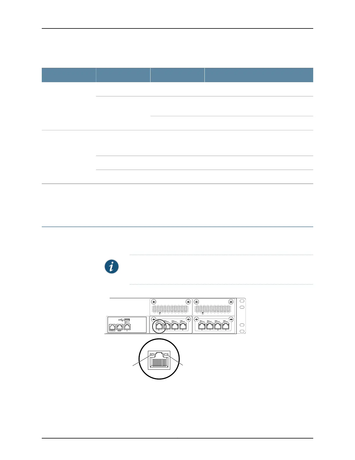
Network Module Port LEDs on a QFX3100 Director Device
The network module ports (labeled 0 through 3) on QFX3100 Director device have two
LEDs that indicate link speed and activity (see Figure 128 on page 383).
NOTE: Figure 128 on page 383 shows the RJ-45 network module ports. The
LEDs on the SFP network module ports are identical.
Figure 128: Network Module Port LEDs on a QFX3100 Director Device
g050055
USB
LINK/
ACT
SPD
0
Link/Activity
LED
Speed
LED
Table 69 on page 384 describes the network module port LEDs.
383Copyright © 2012, Juniper Networks, Inc.
Chapter 30: Viewing QFX3100 System Information