To interconnect two Virtual Chassis for QFabric system control plane redundancy (see
Figure 80 on page 271):
WARNING: Do not look directly into a fiber-optic transceiver or into the ends
of fiber-optic cables. Fiber-optic transceiversand fiber-optic cablesconnected
to transceivers emit laser light that can damage your eyes.
1. If the fiber-optic cable connector is covered by a rubber safety cap, remove the cap.
Save the cap.
2. Remove the rubber safety cap from the SFP+ optical transceiver in port 0 on member 0
of the first Virtual Chassis. Save the cap.
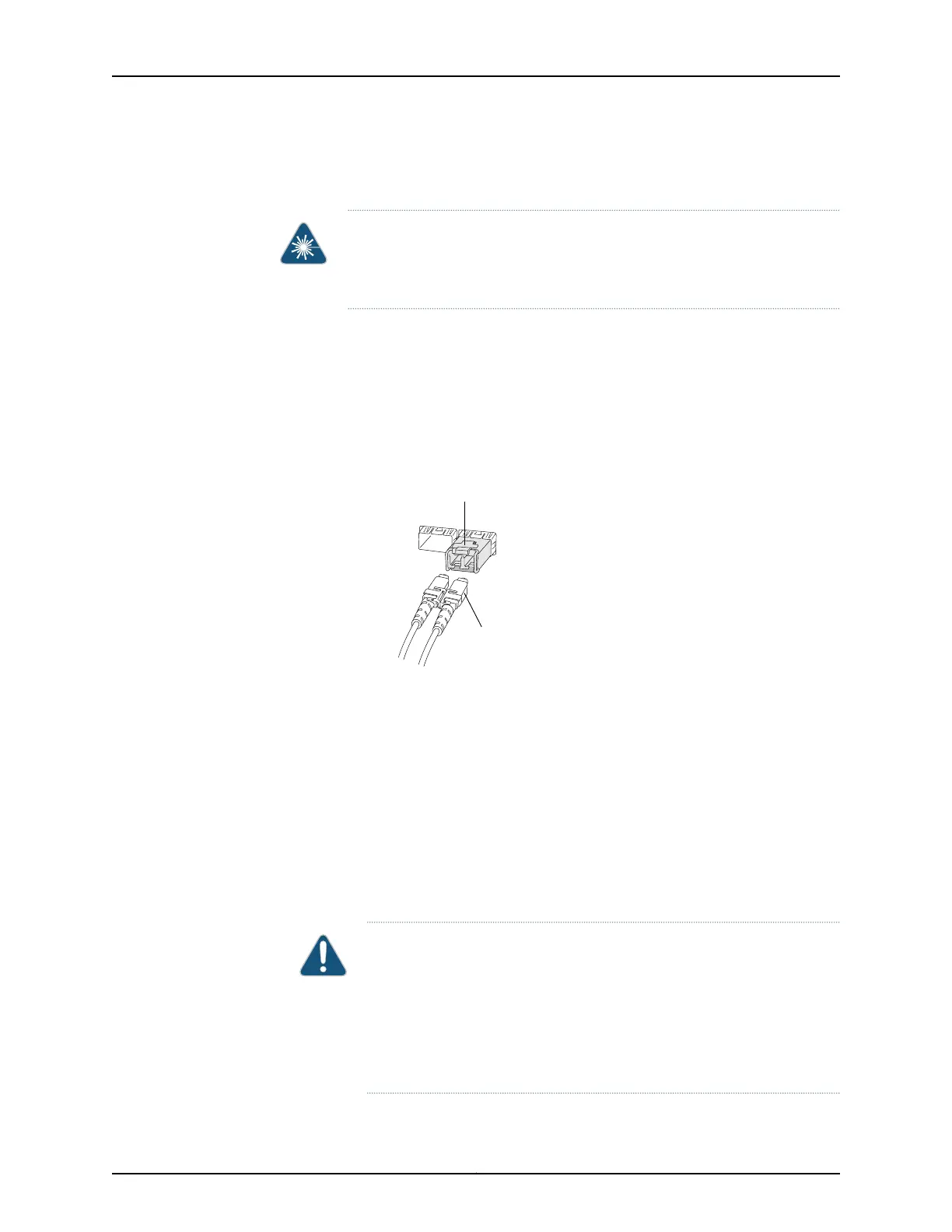
3. Insert the cable connector into the optical transceiver (see Figure 81 on page 273).
Figure 81: Connecting a Fiber-Optic Cable to an Optical Transceiver
Installed in an EX Series Switch
g027016
Fiber-optic cable
Transceiver
4. If the connector at the other end of the fiber-optic cable is covered by a rubber safety
cap, remove the cap. Save the cap.
5. Remove the rubber safety cap from the SFP+ optical transceiver in port 0 on member 0
of the second Virtual Chassis. Save the cap.
6. Insert the cable connector into the optical transceiver.
7. Repeat Step 1 through Step 6 for each uplink module port, following the port
assignments in Table 63 on page 272.
8. Secure the cables so that they are not supporting their own weight. Place excess cable
out of the way in a neatly coiled loop. Placing fasteners on a loop helps cables maintain
their shape.
CAUTION: Do not bend fiber-optic cables beyond their minimum bend
radius.An arc smaller than a fewinches in diameter can damagethe cables
and cause problems that are difficult to diagnose.
Do not let fiber-optic cables hang free from the connector. Do not allow
fastened loops of cables to dangle, which stresses the cables at the
fastening point.
273Copyright © 2012, Juniper Networks, Inc.
Chapter 22: Cabling the QFabric Switch