CAUTION: Ensure that you push the ejector levers evenly and that both
ejector levers are completely engaged. It is possibleforthe board to receive
power if onlyone of the leversis fullyclosed, causinga devicemalfunction.
8. Verify that the front card is installed correctly and functioning normally by checking
the LEDs on the faceplate of the front card. The STATUS LED and POWER LED should
be lit steady green a few minutes after the front card is installed.
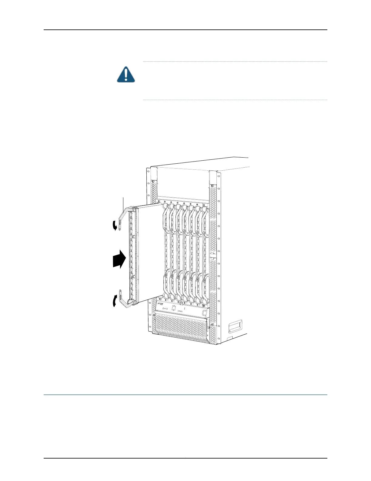
Figure 115: Installing 16-Port QSFP+ Front Card in a QFX3008-I
Interconnect Device
FXIC08
g050114
Ejector
lever
Related
Documentation
16-Port QSFP+ Front Cards in a QFX3008-I Interconnect Device on page 48•
• 16-Port QSFP+ Front Card LEDs on a QFX3008-I Interconnect Device on page 391
Taking the Rear Card Offline in a QFX3008-I Interconnect Device
To prevent data loss, we recommend that you take a rear card offline before removing
it from a QFX3008-I Interconnect device.
355Copyright © 2012, Juniper Networks, Inc.
Chapter 26: Replacing QFX3008-I Components