within 2 minutes of removing the fan tray to prevent overheating of the
chassis.
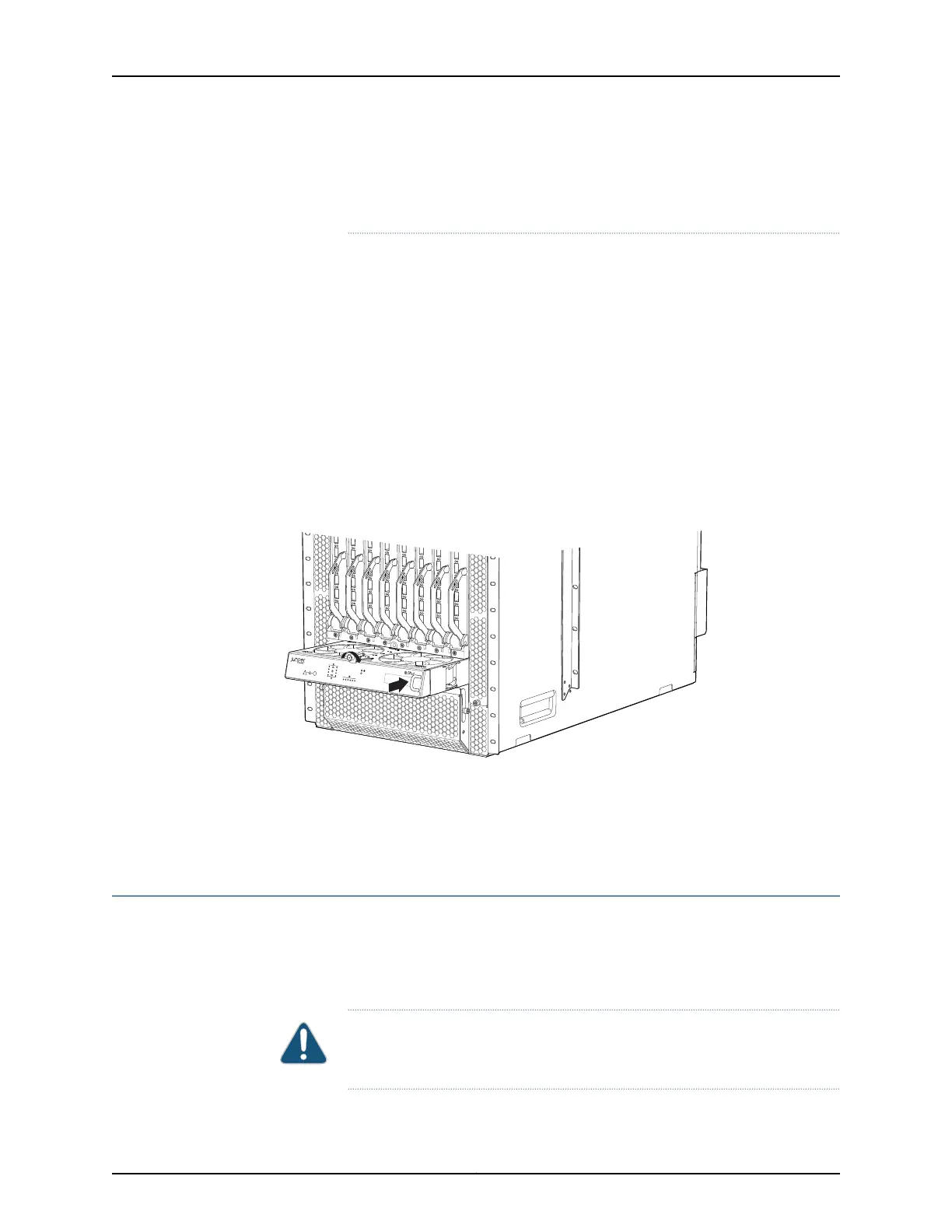
To install a fan tray in a QFX3008-I Interconnect device (see Figure 101 on page 332):
1. Attach the ESD grounding strap to your bare wrist, and connect the strap to the ESD
point on the chassis.
2. Hold the handle of the fan tray with one hand and support the weight of the tray with
the other hand. Align the tray with the fan tray guides on the fan tray slot. Slide in the
fan tray until it is fully seated in the chassis.
3. Tighten the captive screw on the panel display using your fingers.
Figure 101: Installing a Bottom Fan Tray in a QFX3008-I Interconnect
Device
FXIC08
STATUS
FANTRAY FXIC08-FANB
Related
Documentation
Removing a Bottom Fan Tray and Front Panel Display from a QFX3008-I Interconnect
Device on page 329
•
• Cooling System and Airflow in a QFX3008-I Interconnect Device on page 44
Removing a Side Fan Tray from a QFX3008-I Interconnect Device
A QFX3008-I Interconnect device has eight field-replaceable side fan trays. All eight side
fan trays are hot-removable and hot-insertable field-replaceable units (FRUs); you can
remove and replace the fan tray while the device is running without turning off power to
the device or disrupting device functions.
CAUTION: Do not remove a fan tray unless you have a replacement fan tray
available.
Copyright © 2012, Juniper Networks, Inc.332
QFX3000 Hardware Documentation