NOTE: The numerical identifiers for each Node device below are not
preassigned to the Node devices that are shipped to you. They represent
the order in which you connect the Node devices. For example, the first
Node device port you connect (Node 0) will be connected to port ge-0/0/0
on Virtual Chassis member 0.
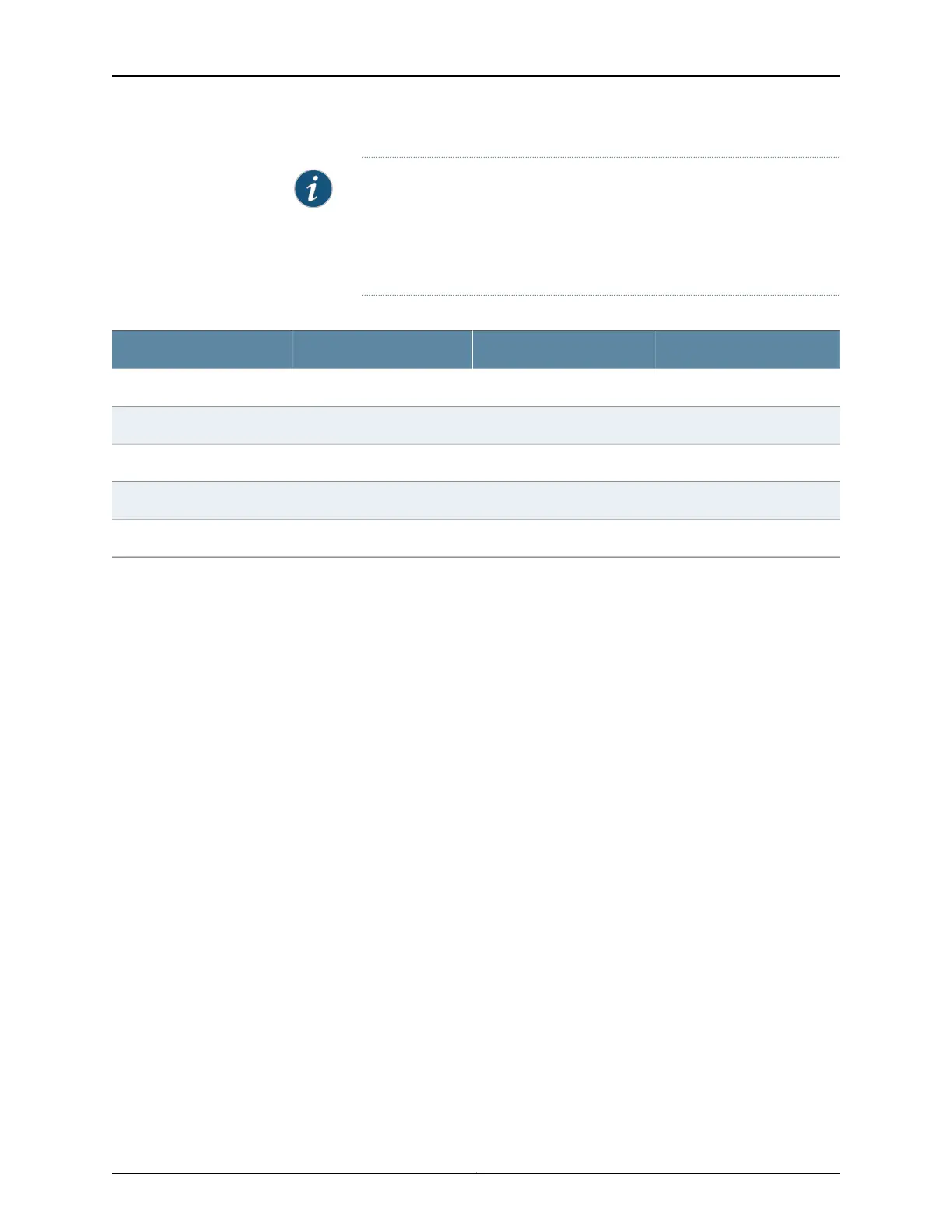
Table 66: QFX3500 Node Device-to-Virtual Chassis Control Plane Port Assignments
Member 3Member 2Member 1Member 0
Node 96: ge-3/0/0Node 64: ge-2/0/0Node 32: ge-1/0/0Node 0: ge-0/0/0
Node 97: ge-3/0/1Node 65: ge-2/0/1Node 33: ge-1/0/1Node 1: ge-0/0/1
............
Node 126: ge-3/0/30Node 94: ge-2/0/30Node 62: ge-1/0/30Node 30: ge-0/0/30
Node 127: ge-3/0/31Node 95: ge-2/0/31Node 63: ge-1/0/31Node 31: ge-0/0/31
To connect a QFX3500 Node device to the control plane network (see Figure 85 on
page 282):
1. Connect one end of the first RJ-45 patch cable to the first management port (labeled
C0) on the Node device management board.
2. Connectthe other end of thatcable to the appropriate member and port on the Virtual
Chassis. See Table 66 on page 283.
3. Connect one end of the second RJ-45 patch cable to the second management port
(labeled C1) on the Node device management board.
4. Connect the other end of that cable to the appropriate member and port on the second
Virtual Chassis. This should be the same member number and port number that you
connected to in Step 2. For example, if you connected the first cable to ge-0/0/0 on
Member 0 on the first Virtual Chassis, you connect the second cable to ge-0/0/0 on
Member 0 on the second Virtual Chassis.
5. Repeat this procedure for each QFX3500 Node device.
Related
Documentation
Connecting a QFX3008-I Interconnect Device to the Control Plane Network on page 278•
• Connecting a QFX3500 Node Device to a QFX3008-I Interconnect Device on page 284
• Connecting QFX3100 Director Devices to the Control Plane Network on page 275
283Copyright © 2012, Juniper Networks, Inc.
Chapter 22: Cabling the QFabric Switch