1. Ensure that the QFX3500 device is powered off (see “Powering Off a QFX3500 Device”
on page 298).
2. Attach the ESD grounding strap to your bare wrist and to a site ESD point.
3. Taking care not to touch the connectors, remove the management board from its bag.
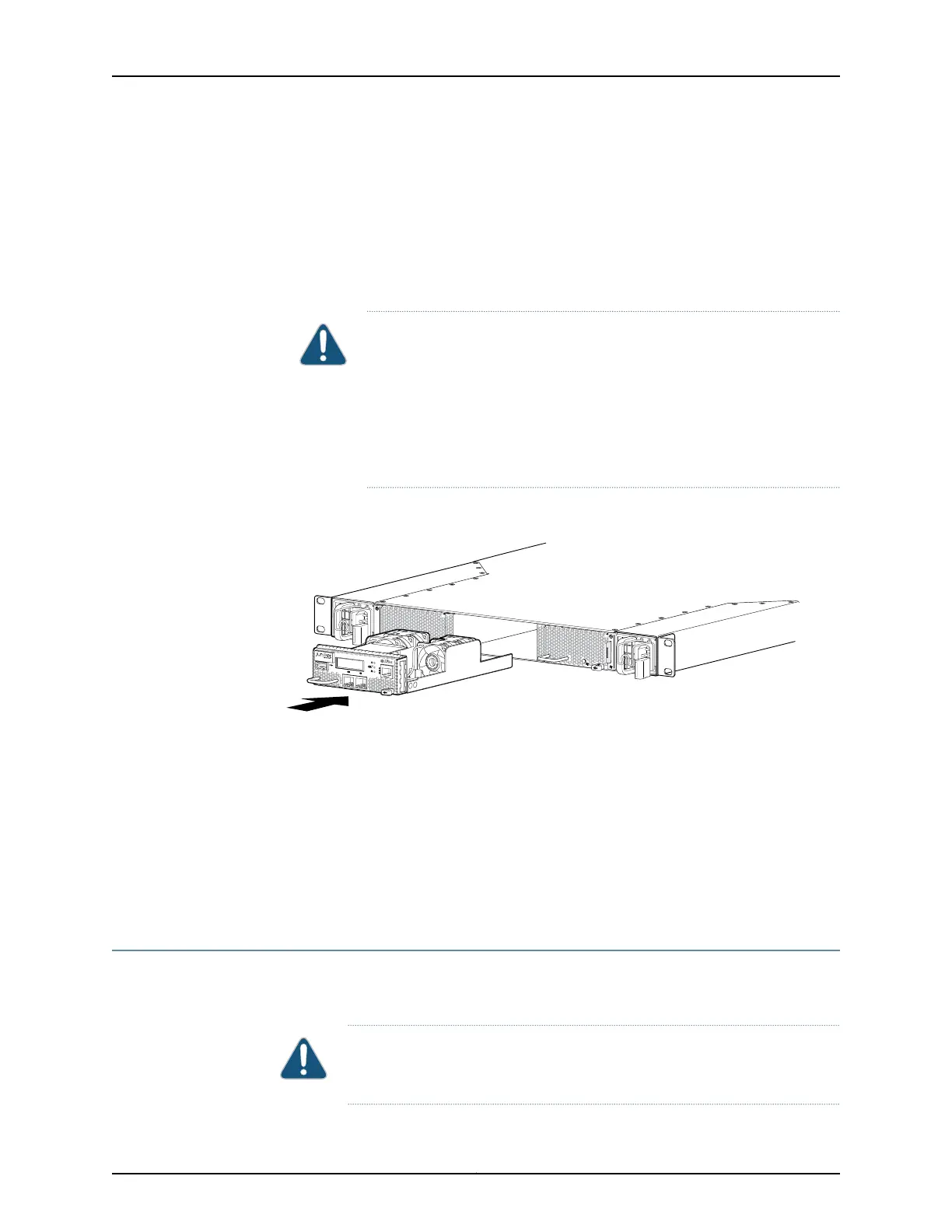
4. Using both hands, align the tray with the management board slot on the front panel
of the chassis and slide it in until it is fully seated and the locking lever slides into place.
CAUTION: Damage can occur if you attempt to install a management
board into a chassis with a different airflow direction. Check the device
model to ensure that you are installing a management board with the
same airflow direction as the chassis. The management boards are
designed so that they can onlybe inserted into the QFX3500device model
that supports the same airflow type. See “Cooling System and Airflow for
a QFX3500 Device” on page 68 for more information.
Figure 122: Installing a Management Board in a QFX3500 Device
Related
Documentation
Management Board for a QFX3500 Device on page 71•
• Field-Replaceable Units in a QFX3500 Device on page 63
• Connecting a QFX Series Device to a Management Console on page 285
• Connecting a QFX3500 Node Device to the Control Plane Network on page 282
• Connecting a QFX3500 Device to a Network for Out-of-Band Management
• Removing a Management Board from a QFX3500 Device on page 369
Removing a Management Board from a QFX3500 Device
QFX3500 devices have a single field-replaceable unit (FRU) management board on the
front panel.
CAUTION: You must power off the QFX3500 device before replacing the
management board.
369Copyright © 2012, Juniper Networks, Inc.
Chapter 27: Replacing QFX3500 Components