To remove a wiring tray from a QFX3008-I Interconnect device (see Figure 98 on page327):
1. Set the wiring tray power switch to the OFF (O) position.
2. If the AC power source has a power switch, set it to the OFF (O) position, and unplug
the power cord or cords from the AC power source.
3. Attach the ESD grounding strap to your bare wrist, and connect the strap to the ESD
point on the chassis.
4. Unscrew the captive screw, located at the top of each wiring tray, counterclockwise
using your fingers. If you cannot easily unscrew the captive screw with your fingers,
use the screwdriver.
5. Taking care not to touch wiring tray components, pins, leads, or solder connections,
place one hand under the wiring tray to support it. Grasp the wiring tray handle with
your other hand, depress the tab at the top of the wiring tray, and pull the wiring tray
completely out of the chassis.
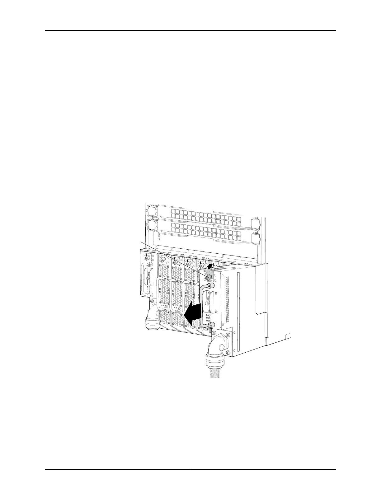
Figure98: Removing a Wiring Tray from a QFX3008-I Interconnect Device
g050148
Loosen
thumbscrew
and depress
the tab.
Related
Documentation
Wiring Tray in a QFX3008-I Interconnect Device on page 54•
• Installing a Wiring Tray in a QFX3008-I Interconnect Device on page 328
327Copyright © 2012, Juniper Networks, Inc.
Chapter 26: Replacing QFX3008-I Components