CAUTION: The fan trays can be removed and replaced while the QFX3008-I
Interconnect device is operating. However, you must replace the fan tray
within 2 minutes of removing the fan tray to prevent overheating of the
chassis.
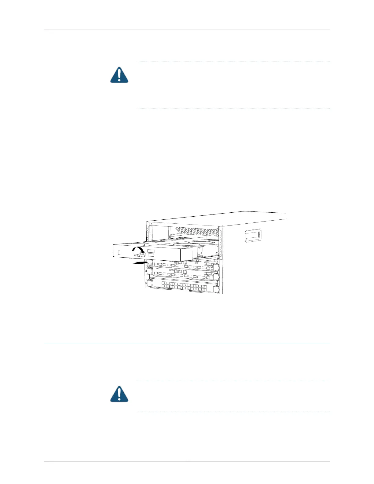
To install a fan tray in a QFX3008-I Interconnect device (see Figure 105 on page 338):
1. Attach the ESD grounding strap to your bare wrist, and connect the strap to the ESD
point on the chassis
2. Align the tray with the fan tray guide on the top of the tray. Slide in the fan tray until
it is fully seated in the chassis.
3. Turn the latch, located in the middle of the fan tray, clockwise to lock the fan tray in
the chassis.
4. Close the cover door and tighten the captive screws on the faceplate using your fingers.
Figure 105: Installing a Top Fan Tray in a QFX3008-I Interconnect Device
Related
Documentation
Removing a Top Fan Tray from a QFX3008-I Interconnect Device on page 336•
• Cooling System and Airflow in a QFX3008-I Interconnect Device on page 44
Removing a Bottom Air Filter from a QFX3008-I Interconnect Device
A QFX3008-I Interconnect device bottom air filter is located beneath the bottom fan
tray and front panel display. There are two captive screws on either side of the air filter
door that secure the air filter in the chassis.
CAUTION: Do not run the devicefor more than 2 minutes without the air filter
in place.
Copyright © 2012, Juniper Networks, Inc.338
QFX3000 Hardware Documentation