of a link or activity on the port and the port status. See “Network Module Port LEDs on a
QFX3100 Director Device” on page 383.
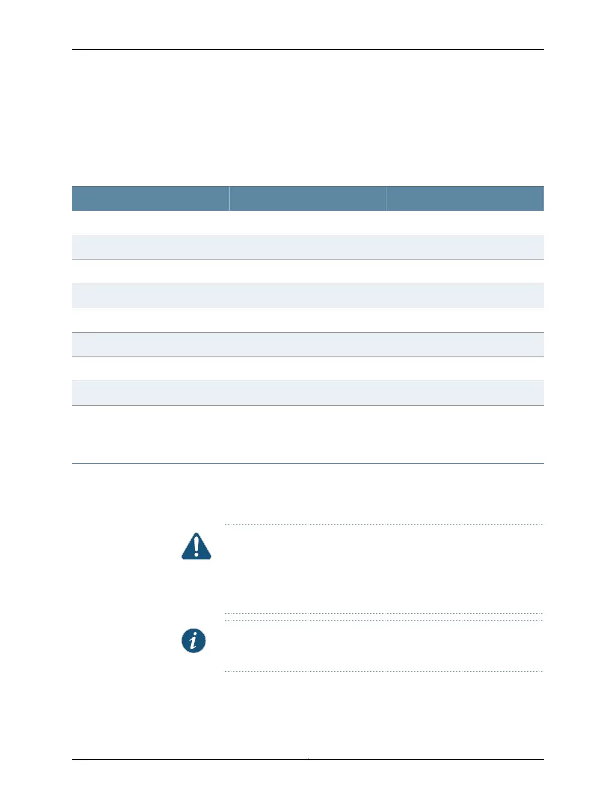
Table 31 on page 108 provides the pinout information for the network module’s RJ-45
connector.
Table 31: Network Port Connector Pinout Information for a QFX3100 Director Device
DescriptionSignalPin
Transmit/receive data pair 1TRP1+1
Transmit/receive data pair 1TRP1-2
Transmit/receive data pair 2TRP2+3
Transmit/receive data pair 3TRP3+4
Transmit/receive data pair 3TRP3-5
Transmit/receive data pair 2TRP2-6
Transmit/receive data pair 4TRP4+7
Transmit/receive data pair 4TRP4-8
Related
Documentation
Front Panel of a QFX3100 Director Device on page 26•
Interface Specifications for SFP+ Transceivers for QFX3500 Device Access Ports
Access ports in QFX3500 devices support SFP and SFP+ transceivers. This topic describes
the optical interfaces supported for those transceivers. It also specifies the copper
interface supported for the SFP transceivers.
CAUTION: Do not place a copper transceiver in an access port directly above
or below another copper transceiver. Internal damage to the access ports
and device can occur. Because of this limitation, a maximum of 18 copper
transceivers can be installed in ports 6 through 41. We recommend using only
the top row of access ports for copper transceivers.
NOTE: Use only transceivers purchased from Juniper Networks for your QFX
Series device.
The optical transceivers installed in QFX3500 devices support digital optical monitoring
(DOM): you can view the diagnostic detailsfor these transceivers by issuing the operational
Copyright © 2012, Juniper Networks, Inc.108
QFX3000 Hardware Documentation