Related
Documentation
Control Board in a QFX3008-I Interconnect Device on page 49•
• Taking a Control Board Offline in a QFX3008-I Interconnect Device on page 345
• Removing a Control Board from a QFX3008-I Interconnect Device on page 347
• request chassis beacon
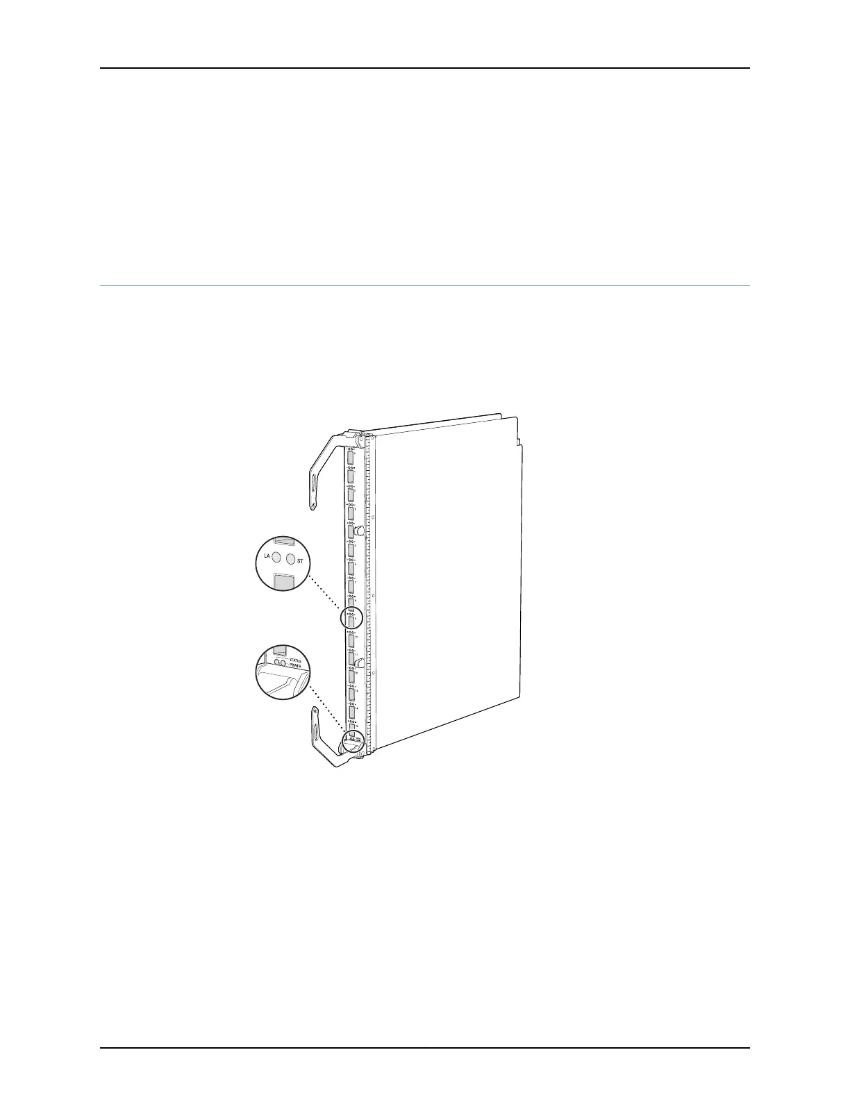
16-Port QSFP+ Front Card LEDs on a QFX3008-I Interconnect Device
Each 16-port QSFP+ front card has two LEDs at the bottom of the module front panel
that indicate front card status. Each QSFP+ port has two LEDs that indicate link status
and activity. See Figure 132 on page 391.
Figure 132: 16-Port QSFP+ Front Card LEDs on a QFX3008-I Interconnect
Device
g050153
Link/Activity
and Status LEDs
Front card
status LEDs
Table 74 on page 392 describes these LEDs, their colors and states, and the status they
indicate.
391Copyright © 2012, Juniper Networks, Inc.
Chapter 31: Viewing QFX3008-I System Information