•
Allow at least 6 in. (15.2 cm) of clearance on the side between devices that have fans
or blowers installed. Allow 2.8 in. (7 cm) between the side of the chassis and any
non-heat-producing surface such as a wall. For the cooling system to function properly,
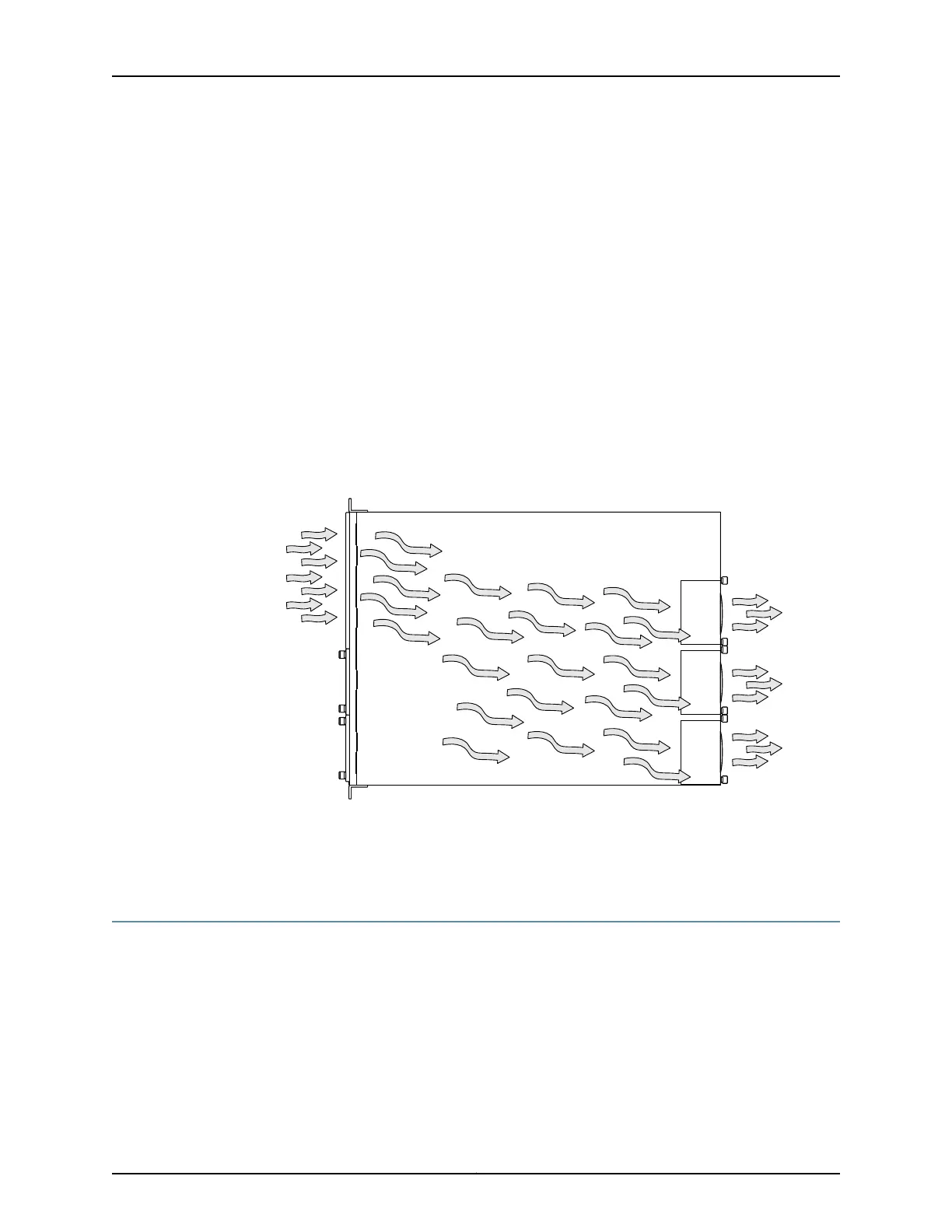
the airflow around the chassis must be unrestricted. Figure 48 on page 100 shows the
airflow through the QFX3100 Director device.
•
If you are mounting a QFX3100 Director device on a rack or cabinet with other
equipment, or if you are placing it on the desktop or floor near other equipment, ensure
that the exhaust from other equipment does not blow into the intake vents of the
chassis.
•
Leave at least 24 in. (61 cm) both in front of and behind the QFX3100 Director device.
For service personnel to remove and install hardware components, you must leave
adequate space at the front and back of the QFX3100 Director device. NEBS GR-63
recommends that you allow at least 30 in. (76.2 cm) in front of the rack or cabinet and
24 in. (61 cm) behind the rack or cabinet.
Figure 48: Airflow Through the QFX3100 Director Device
Related
Documentation
Cooling System and Airflow in a QFX3100 Director Device on page 27•
Clearance Requirements for Airflow and Hardware Maintenance for a QFX3008-I
Interconnect Device
When planning the site for installing a QFX3008-I Interconnect device, you must allow
sufficient clearance around the device.
Follow these clearance requirements:
•
For the cooling system to function properly, the airflow around the chassis must be
unrestricted. Do not block the air intake or exhaust areas shown in Figure 49 on page 101
and Figure 50 on page 101.
Copyright © 2012, Juniper Networks, Inc.100
QFX3000 Hardware Documentation