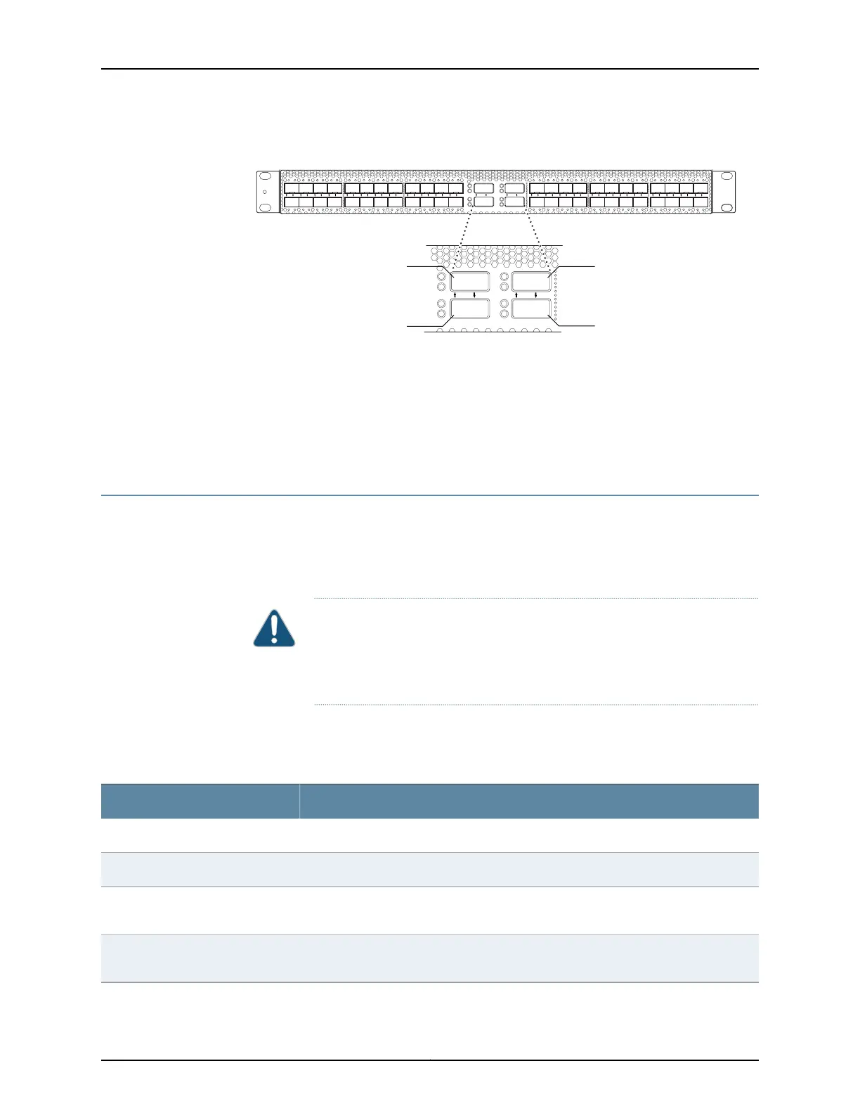
Figure 33: QSFP+ Uplink Port Locations
QSFP+ ports
LA
ST
LA
ST
LA
ST
LA
ST
Q0 Q1 Q2 Q3 24 25 26 27 28 29 30 31 32 33 34 35 36 37 38 39 40 41 42 43 44 45 46 470 1 2 3 4 5 6 7 8 9 34 35 36 37 38 39 40 41 42 43 44 45 46 47
LA
ST
LA
ST
LA
ST
LA
ST
Q0 Q1 Q2 Q3
g050023
xe-0/1/1
through xe-0/1/3
xe-0/1/4
through xe-0/1/7
xe-0/1/8
through xe-0/1/11
xe-0/1/12
through xe-0/1/15
Related
Documentation
Field-Replaceable Units in a QFX3500 Device on page 63•
• Site Preparation Checklist for a QFX3500 Device on page 86
• Access Port and Uplink Port LEDs on a QFX3500 Device on page 399
• Installing and Removing QFX3500 Device Hardware Components on page 361
Field-Replaceable Units in a QFX3500 Device
Field-replaceable units (FRUs) are components that you can replace at your site. The
QFX3500 device FRUs except the management board are hot-insertable and
hot-removable: you can remove and replace them without powering off the device or
disrupting the switching function.
CAUTION: Replace a failed power supply with a blank panel or new power
supply within 1 minute of removal to prevent chassis overheating. Replace a
failed fan tray with a new fan tray within 1 minute of removal to prevent
chassis overheating.
Table 9 on page 63 lists the FRUs for the QFX3500 device and actions to take before
removing them.
Table 9: FRUs in a QFX3500 Device
Required ActionFRU
None.Power supplies
None.Fan trays
You must power off the QFX3500 device before replacing the management board. See
“Removing a Management Board from a QFX3500 Device” on page 369.
Management board
None. We recommend that you disable the interface using the set interface-name disable
command. See “Disconnecting a Fiber-Optic Cable from a QFXSeries Device” on page 376.
Optical transceivers
63Copyright © 2012, Juniper Networks, Inc.
Chapter 4: QFX3500 Overview