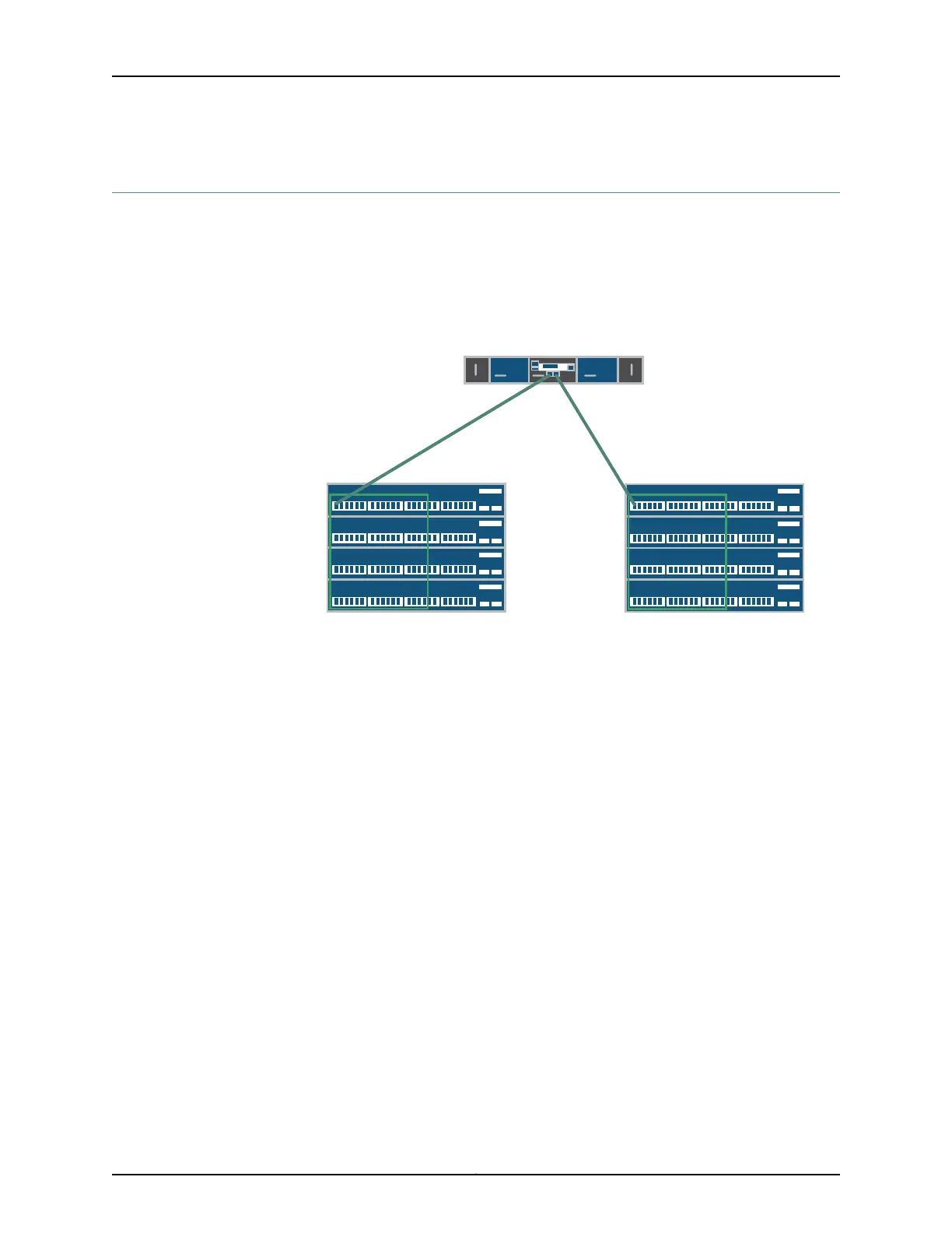
Connecting a QFX3500 Node Device to the Control Plane Network
A QFX3000 QFabric system control plane and management network is formed by
connecting the QFX series devices in your network to two Virtual Chassis composed of
four EX4200 switches each. QFX3500 Node devices have two management ports with
RJ-45 connectors. Use the management ports to connect the QFX3500 Node device to
each Virtual Chassis (see Figure 85 on page 282).
Figure 85: QFX3500 Node Device Control Plane Connections
VC0
VC1
ge-0/0/0
ge-0/0/0
C1
C0
g041121
Before you begin to connect a QFX3500 Node device to the control plane network:
•
Install your QFabric system hardware (Director group, Interconnect devices, and Node
devices). For more information, see “Installing and Connecting a QFX3100 Director
Device” on page 213, “Installing and Connecting a QFX3008-I Interconnect Device” on
page 223, and “Installing and Connecting a QFX3500 Device” on page 259.
•
Install your Virtual Chassis hardware (EX4200 switches). For more information, see
Installing and Connecting an EX4200 Switch.
•
Create two Virtual Chassis switches of four members each. For more information, see
Configuring an EX4200 or EX4500 Virtual Chassis (CLI Procedure).
•
Interconnect the two Virtual Chassis switches using the 10-Gigabit Ethernet SFP+
uplink ports. For more information, see “Interconnecting Two Virtual Chassis for QFabric
System Control Plane Redundancy” on page 271.
•
Ensure that you have two RJ-45 patch cables available. For cable specifications, see
“Cable Specifications for Control Plane Connections for the QFX Series” on page 129.
•
Use Table 66 on page 283 to determine the QFX3500 Node device-to-Virtual Chassis
port mappings. Specific ports have been reserved on the Virtual Chassis to connect to
each of the QFabric system device types. Such design simplifies installation and
facilitates timely deployment of a QFabric system. It also permits the use of a standard
Virtual Chassis configuration (see Example: Configuring the Virtual Chassis for the
QFabric Switch Control Plane).
Copyright © 2012, Juniper Networks, Inc.282
QFX3000 Hardware Documentation