c. Tighten the screws on the power supply terminals until snug using the screwdriver.
Do not overtighten—apply between 5 in-lb (0.56 Nm) and 6 in-lb (0.68 Nm) of
torque to the screws.
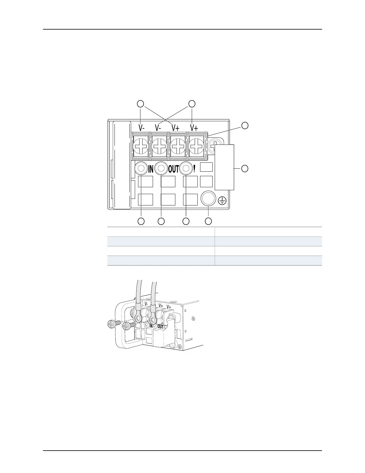
Figure 78: DC Power Supply Faceplate for a QFX3500 Device
5—1— ESD grounding pointFeed A input terminals
6—2— Fault LEDFeed B input terminals
7—3— Output LEDTerminal block
8—4— Input LEDEjector lever
Figure 79: Securing Ring Lugs to the Terminals on the DC Power Supply
8. Replace the terminal block cover.
9. Close the input circuit breaker.
10. Verify that the IN and OUT LEDs on the power supply are lit green and are on steadily.
Related
Documentation
• DC Power Supply for a QFX3500 Device on page 75
• DC Power Supply LEDs on a QFX3500 Device on page 403
Copyright © 2012, Juniper Networks, Inc.270
QFX3000 Hardware Documentation